Removing
On air-conditioned cars, the air conditioning compressor and condenser should be removed and set aside without disconnecting refrigerant lines, as described below, before removing the engine and transaxle. On cars with power steering, dismount the power steering pump and fluid reservoir, and set them aside without disconnecting the power steering fluid lines.
On cars with automatic transmissions, if the engine and transaxle are going to be separated, the torque converter drive plate needs to be marked for reinstallation. It may be easier to do this prior to removing the engine and transaxle. Mark the drive plate with the engine at Top Dead Center (TDC).
To remove:
| 1. | Disconnect the negative (-) battery terminal, and then the positive (+) terminal. Remove the battery. |
| 2. | Working under the car, disconnect the drive axle inner constant velocity joints from the transaxle drive flanges, as described in SUSPENSION AND STEERING. Suspend the axles from the body with stiff wire to avoid damage to the outer constant velocity joints. |
| 4. | Drain the cooling system as described in COOLING SYSTEM, and remove the coolant hoses connected to the engine. |
| 5. | On gasoline engines, remove fuel injection components as described in 4.8 Removing and Installing Cylinder Head. With the main fuel lines attached, remove the air flow sensor and air filter housing and set it aside. |
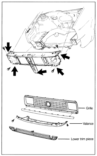
| 6. | Remove the lower apron bolt and unclip the lower trim piece. See Fig. 5-1. |
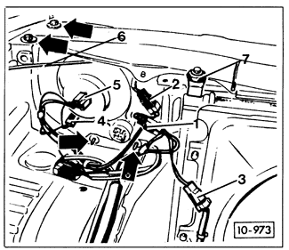
| 7. | Disconnect the electrical connectors for the radiator cooling fan, the radiator thermoswitch, and the headlights. Disconnect the hood release cable and the upper radiator mounts. See Fig. 5-2. |
| Fig. 5-1. | Front apron (radiator support) mounting points (arrows). Lower trim piece and grille snap in place. |
|
| Fig. 5-2. | Items to be disconnected for removal of front apron. Connectors 1 and 2, radiator cooling fan plug 3, headlight connections 4 and 5, hood release cable from hood latch 6, radiator mounts 7, and front apron mounting bolts (arrows). |
|
| 8. | Remove the grill and the front apron. Remove the radiator with air ducts and fan shroud, as described in COOLING SYSTEM. |
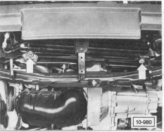
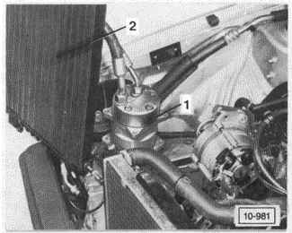
| 9. | On cars with air conditioning, remove the condenser mounting bolts as shown in Fig. 5-3. Without disconnecting any refrigerant lines, remove the condenser and remove the air conditioning compressor from the engine. Set them aside as shown in Fig. 5-4, using care to avoid kinking the refrigerant lines. |
| Fig. 5-3. | Air conditioning condenser mounting bolts (arrows). |
|
| Fig. 5-4. | Air conditioning compressor and condenser set aside for engine removal with refrigerant lines still connected. Tie in place. Use padding to protect paint. |
|
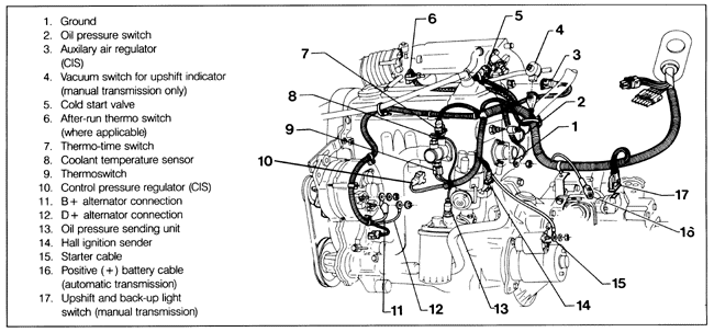
| 10. | Disconnect all remaining electrical connections to the engine and transaxle. Typical engine and transaxle connections are shown in Fig. 5-5. For diesel fuel injection connections, see FUEL SYSTEM-DIESEL. |
| Fig. 5-5. | Engine and transaxle items to be disconnected 8-valve gasoline engine shown. Other engines are similar. |
|
| 11. | On turbo diesel engines, detach the air cleaner duct from the turbocharger's air intake. Remove the air cleaner assembly and detach the electrical connector from the blow-off valve. |
| 12. | On 1985-1989 16-valve and California models, disconnect the engine vibration damper from the engine block and the right-side shock absorber tower in the engine compartment. On 1.8 liter 16-valve engines, code PL, remove the upper intake manifold, as described in 4.1 Cylinder Head Cover and Gasket. |
| 13. | On gasoline engines, disconnect the oxygen sensor connector behind the cylinder head. Remove and label the ignition coil connectors. Remove all engine ground connections. |
| 14. | Remove the speedometer drive cable from the transaxle housing. On models with manual transmission, detach the clutch cable and shift linkage as described in MANUAL TRANSMISSION AND CLUTCH. |
| 15. | On models with automatic transmissions, place the selector lever in the "Park" position. Remove the accelerator cable and the selector lever cable as shown in AUTOMATIC TRANSMISSION. |
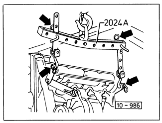
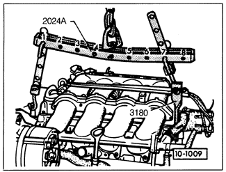
| 16. | Install an engine lifting device, using the lifting points illustrated in Fig. 5-6 and, for 16-valve engines, Fig. 5-7 or Fig. 5-8. |
| Fig. 5-6. | Engine hoist chain properly attached for lifting gasoline and diesel engines, except 16-valve. |

|
| Fig. 5-7. | Engine hoist (Volkswagen special tool no. 2024A) installed on 1.8 liter 16-valve engine, code PL. Use of hoist as shown is necessary for proper weight distribution. Always use securing cotter pins and holding pins, as shown. |
|
| Fig. 5-8. | Engine hoist (Volkswagen special tool no. 2024A) installed on 2.0 liter 16-valve engine, code 9A. Use of special tool 3180 permits engine to be removed without removing intake manifold. |
|
| 17. | Raise the hoist slightly, so that the weight of the engine and transaxle assembly is supported by it. |
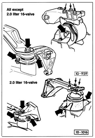
| 18. | Remove the bolts from the rear engine mount and the transaxle mounting as shown in Fig. 5-9. |
| Fig. 5-9. | Rear engine mounting bolts (right) and transaxle mounting bolts (left). The rear engine mount is attached to passenger-side of subframe behind engine. Transaxle mount is attached to transaxle and left side subframe. |
|
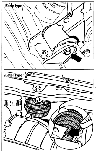
| 19. | Remove the front engine mounting nut or bolt as shown in Fig. 5-10. |
| Fig. 5-10. | Front engine mounting (arrows). Early type (top) uses rubber bushing. Later type (bottom) is hydraulic mount. |
|
| 20. | Raise and remove the engine and transaxle assembly from the car. Proceed slowly. Check frequently to make sure no hoses or wires are interfering with engine removal. If the car has been raised on jack stands, check often see that it remains stable and adequately supported. |
|


