Руководство How to Read Wiring Diagrams - Symbols, Layout and Navigation

Admin

Admin

Создатель сайта
Команда форума
Сообщения
11 340
Реакции
4 569
Город
Россия, Москва
Авто
VW Tiguan 2.0 DBGC 2018, VW Touran 1.6 BSE 2008
How to Read Wiring Diagrams
Self-Study Program
(для перевода используйте в браузере правую кнопку мыши -> "перевести на русский" )

Introduction
Wiring Diagram Overview, Layout
Navigation
Elements of a wiring diagram, Symbols, DIN 72 552
Introduction to Conductors, Wires, Wire colors, Wire sizes, Other Conductor descriptions
Connector Pin Assignments
Components
Layout
Practical Examples
Navigation 1, Navigation 2
Navigation 3, Navigation 4
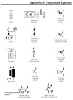
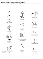
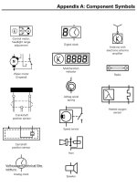
Appendix A: Component Symbols
Appendix B: Wiring Connections
Appendix C: Component Codes and Wiring
Appendix D: DIN Standards.
Appendix E: Wiring Diagrams
Glossary

Course goals

This course will enable you to:
• Follow current from its power source to the Ground point quickly and accurately.
• Understand the symbols of common components and circuit designations used in Volkswagen Wiring Diagrams.
• Practice Wiring Diagram navigation through practical exercises and hands on examples.


Introduction

As today’s vehicles become increasingly complex, so does the job of the technician.
Wiring diagram navigation skills are critical to diagnosing and repairing today’s vehicle in a timely and accurate manner.

This Self Study Program is not intended to instruct the technician how the electrical system operates in a vehicle.
Given an understanding of electrical operation, this Self Study Program will introduce you to the skills necessary to read Volkswagen wiring diagrams.

In this program you will be exposed to all aspects of wiring diagrams, including:
• Commonly used symbols and their meanings
• Current tracks, including how to follow circuits between pages or diagrams
• Component identification
• DIN standards for terminal designations
• Wiring color codes and gauge (size)
• Terminal identification on both connectors and components
 
Последнее редактирование:
Wiring Diagram Overview

Overview

Volkswagen wiring diagrams are a graphic representation of the actual vehicle wiring.
They are developed from the engineering drawings that are used to produce the wiring harness. A consistent set of symbols are used to represent the actual components and conductors.
Volkswagen electrical systems and wiring diagrams follow the German DIN (Deutsche Industrie Norm/Deutsches Institut für Normung) standards.
These standards are guidelines for manufacturing in Germany, similar to SAE (Society of Automotive Engineers) in the United States.

Layout
The layout of wiring diagrams is common to all Volkswagen vehicles. Called “Current Track” wiring diagrams, they show the power source at the top of the page and the Ground points at the bottom.
Situated vertically between power and Ground are the current tracks, which contain electrical components and conductors.
This current track layout simplifies the wiring diagram. Conductor symbols crossing where they do not connect is kept to a minimum.
Refer to the example on page 3 for the basic layout of the wiring diagram.

Central/relay panel
The central/relay panel is indicated in gray at the top of the wiring diagram page.
The central/relay panel includes common power circuits, such as battery power (30), ignition switched power (15), load reduction (75/X), and Ground (31).

Ground Connections
Ground connections are represented as a line at the bottom of the wiring diagram page, directly above the current track numbers.
All Ground connections, whether they occur as a splice in a harness, or the final Ground source, are numbered and identified in the wiring diagram.

Conductors and components
Between the central/relay panel and the vehicle ground at the bottom of the diagram are located the component symbols and conductors.
Components are marked with a component code listed in the legend.
Conductors are generally marked with wire color and size.

Current tracks
Individual current tracks are identified numerically along the base of the wiring diagram.
These numbers are used to find the continuation of a conductor. Where the system or circuit layout is complex, this continuation may be on the same page, or on a different page.
For example, the number 191 inside of the small box on page 3 indicates that the wire is continued on current track 191. Following straight down on the diagram, we see that this wire is on current track 5. If we were to navigate to current track 191, we would see the same color and size wire with a small box containing the number 5.

Legend
Below the current track numbers you’ll find a legend of the components (by component code) found in the specific diagram. This will often detail the location of a given component or connection.
 
Navigation

Navigation in the wiring diagram is based around the use of the current track numbers.
You will generally start with the affected component and then follow the associated circuit from there, tracing Power, Ground, and signals that affect the component’s operation.

1666796349861.png
 
Elements of a wiring diagram

In this section, we will look at how various symbols are used in a wiring diagram to represent the actual components on the vehicle.
Every circuit needs a minimum of the following to operate:
• Power supply
• Consumer (load)
• Ground
• Conductors (usually wire)
If any of these are missing, a complete circuit is broken and the consumer will not function. The ability to break down a circuit
into its individual parts is the key to being able to diagnose failures in the circuit.

Wiring diagrams incorporate many symbols used to illustrate a complete circuit.
These symbols can include:
• Current track numbers
• Components
• Terminal designations
• Conductors
• Connectors
Together these components make up a complete and accurate wiring diagram.

1666796982580.png


Symbols
Graphical representations called "symbols" are used to represent components and conductors in wiring diagrams.
The key to reading wiring diagrams is understanding the symbols.
These symbols are standardized, allowing quick recognition of various components.

DIN Standard 72 552
This standard applies to the terminal designations for circuits.
The purpose of the terminal designation system is to enable accurate connection identification from conductors (wires) to various components when diagnosis and repair is necessary.

Examples of DIN standards for terminal designations are shown below:
1 Ignition coil primary
4 Ignition coil secondary
15 Ignition switched, on and start
30 Battery +
31 Ground
31b Switched Ground
50 Starter control
75/X Load Reduction/Ignition switched on only

The terminal designations do not identify the wires, but the type of circuit.
For this reason, the designations are not placed on the wires in the diagram, but on the component.
Refer to Appendix D on page 36 for a more complete list of terminal standards.
Be aware that some abbreviations are used, and they may be abbreviations of German words.
For example, “GRA” is the abbreviation for “cruise control”, and VL is the abbreviation for “left front.
 
Последнее редактирование:
Introduction to Conductors

The wiring harness and related components may contain many different types of conductors, including wires, internal connections, threaded connections, welded connections, push-on connectors, multiple point connectors and Ground.
The complete list of wiring connections and symbols is shown in Appendix B.

Wires
Wires are conductors that carry current to components, and are usually indicated by a solid line.
A wire shown as a dashed line in a wiring diagram indicates that the wire does not apply to all vehicles, and is noted in the wiring diagram legend.

Wire colors
Knowing the standards for wiring colors makes the job of reading and interpreting them easier.
Some of the common standards include wiring color for specific circuits, as well as the terminal designation.
For example:
Red . . . . . . . . . . . . . . . . . . . Battery +
Green. . . . . . . . . . . . . . . . . . Ignition (1)
Brown . . . . . . . . . . . . . . . . . Ground (31)
Yellow . . . . . . . . . . . . . . . . . Headlights (58)

Once the technician has an understanding of the color guides, the job of isolating systems becomes easier.
Wire colors are shown as abbreviations of the German word for the color.

The following list shows the German abbreviations to the English text for the most common colors.
Refer to appendix C for other color code definitions.
bl . . . . . . . . . . . . . . . . . . . . . Blue
br. . . . . . . . . . . . . . . . . . . . . Brown
ge . . . . . . . . . . . . . . . . . . . . Yellow
gn . . . . . . . . . . . . . . . . . . . . Green
ro. . . . . . . . . . . . . . . . . . . . . Red
sw . . . . . . . . . . . . . . . . . . . . Black
li . . . . . . . . . . . . . . . . . . . . . Violet
ws . . . . . . . . . . . . . . . . . . . . White

Wire sizes
Wiring diagrams also indicate the wire gauge used (shown in mm2), designating the cross sectional area of the wire.
Because standards exist for the maximum permissible voltage drop across a circuit, wire gauge is critical.
If the voltage drop across the wire is too high, one or more of the following may occur:
• The circuit may overheat
• The consumer may not operate properly (due to low voltage condition)
• Components may be damaged

If a wiring repair needs to be made and metric sized wire is not available, the technician may need to use American Wire Gauge (AWG) sized wire.
Note:
• If the exact size wire is not available for a repair, use the next larger size.
• For more information on wiring, refer to the Wiring Harness Inspection and Repair SSP


Other conductor descriptions

Internal conductors
exist inside components, acting as bridges between the wiring harness and the final consumer.
In some components these conductors are labeled in the component. An example would be the 30 circuit (Battery +) in the central/relay panel.
In other components the conductor is not labeled. Internal conductors are shown as thin, black lines.
1666798073220.png


Physical contact

Some components, such as the starter or generator, may receive Ground where they are bolted to the engine or transmission.
This is also shown as a thin black line.

Welded connections are used in wiring harnesses to join multiple, smaller gauge wires to a single larger wire which terminates at the fuse relay panel or chassis Ground.
Sometimes a welded connection is shown with the thin line not terminating at another wire. This symbolizes that this welded connection is used in other diagrams for the car.
The technician may need to reference other diagrams to locate components or Grounds related to this connection.
1666798127439.png


Threaded connectors are commonly used on the bottom of the fuse relay plate to distribute power and Ground to components.
The common connectors include Battery power, Ground and load reduction (X).
1666798195051.png


Ground

The vehicle chassis acts as a common Ground conductor throughout the vehicle,
and is identified by the line at the bottom of the wiring diagram above the current track numbers.

1666798243633.png


Some wiring diagrams will show ground designations at the bottom of the wiring diagram that are actually welded ground connections in the harness
(see illustration SSP 8730/75). In practice, you may need to search through the legend to find where a welded ground connection finally attaches to the vehicle chassis.

1666798307030.png


Other wiring diagrams will show welded Ground connections in the wiring harness, as shown in illustration SSP 8730/79.

1666798348407.png

1666798359817.png
 
Последнее редактирование:
Connector pin assignments

Wiring diagrams tell the user at which pin numbers the wires terminate, simplifying diagnosis.
There are 4 main types of terminal designations:
• Push-on/multi-point connections
• Component/multi-point
• Central/relay panel
• Relay

Push-on/multi-pin connectors use the "T" designation, and are identified in the legend.
For example, T8a/5 designates an 8-pin connector, with the specified wire located in terminal 5 of the connector housing.
The legend will give additional information about this connector. For example: "8-Pin connector, brown, in engine compartment, in wiring duct, left"
(see Wiring Diagram example 41 beginning on page 61 for specific examples).
1666798933189.png


Generally, pin assignments are labeled on the plastic hard-shell connector housing and/or the corresponding component.
On larger connectors, pin assignments are labeled at either end of a row. For example, the Engine Control Module (ECM) plug often has 2 or 3 rows of 12 or more terminals.
Each row will be marked on each end to facilitate easier diagnosis.
1666798955946.png


Component/multi-point pin assignments may or may not use the "T" designation.
Some are numbered sequentially. Others may use DIN circuit designations, or a combination of these methods.
See example at right, and find two examples in wiring diagram 29 (Appendix E).
1666799166622.png

1666799185306.png


Central/relay panel connections enter or exit as either threaded connections, or multipoint connectors.
Threaded connectors are identified in the legend, and may be identified on the component with the DIN circuit designation.

Multi-point connectors on the back of the panel are not identified in the legend.
They will have a letter and possibly a number to identify location, followed by the pin number.
For example S1/5 would be connector S1, pin 5.
1666799222034.png

1666799394964.png


Relay connections list the terminal cavity number on the relay socket, followed by the pin identification on the relay.
Illustration SSP 8730/65 shows that cavity 2 of the harness connector is associated with the DIN terminal 30 of the relay.
Both may be used during diagnosis of the circuit.
1666800218957.png


Note:
When diagnosing electrical concerns using the VAG 1598 pin-out box, the pin numbers on the control module and multi pin connector usually match the pin numbers on the tool.

When using the VAG 1466 pin-out box, the numbers on the relay or control module and socket usually do not match those on the tool.
These must be noted before beginning diagnosis.
1666800281050.png
 
Последнее редактирование:
Components
Components in wiring diagrams are given an alphanumeric designation for identification.
The first portion of the code separates the component into basic groups.
An F for example, designates a switch, while a Z would be used for a heating element.
A complete list of these designations are shown in Appendix C on page 43.
The second part (numeric) designates which component is covered inside of these main groups.

Example: Evaporative Emissions (EVAP) Canister Purge Regulator Valve N80.
N designates a solenoid valve, 80 clarifies which solenoid is being dealt with.

A commonly used symbol is the resistor, used to create a voltage drop in a circuit.
Below are three types of resistors:
A standard resistor has a fixed resistance.
1666800690184.png


A rheostat, or potentiometer, varies its resistance based on mechanical input.
An example of this is the Throttle Position Sensor (TPS) on a Motronic equipped car (SSP 8730/57).
1666800817978.png


A temperature dependent resistor varies its resistance based on temperature.
This type of resistor is used as the Engine Coolant Temperature (ECT) sensor on an engine management system,
or the Interior Temperature sensor on models with climate control (SSP 8730/56).
1666800955649.png


When a resistor is used as a sensor, it generally carries a component designator “G.”

Note:
Any time the temperature symbol (left) is attached to another symbol, it signifies that
the operation of that component will vary with temperature.
1666801331424.png


The switch is another component used to control current flow. The basic symbols for an open and closed switch are shown in illustration SSP 8730/22.
An example of this simple two-position switch would be a glove compartment light switch. A simple switch uses the component designation “F.”
1666801448867.png


There are many types of designs, including mechanically actuated, pressure actuated, temperature actuated and momentary.

Examples include:
• Oil pressure switch (pressure actuated)
1666801582194.png


• Cooling fan thermo-switch (temperature actuated)
1666801696567.png


• Brake Switch -F- (mechanically operated)
1666801777639.png


More complex circuits may require a switch with multiple sets of contacts.
An example of this would be the cruise control switch.
As you can see in illustration SSP 8730/25, there are multiple sets of contacts within the assembly.
1666801993614.png

Depending on the position of the switch, various sets of contacts are open or closed.
Careful study of the symbols allows the technician to follow the circuit through the switch under any condition.
A complex switch uses the component designation “E”.

Note:
All switches and relays are shown in a nonoperated state.


Fuses are used to prevent excessive current from damaging other components in a circuit.
There are various types, including standard fuses, thermal fuses (circuit breakers), and strip fuses.
Fuses use the component designation “S”, their symbols are shown below:
1666802165198.png


The example below shows strip fuses and standard fuses as seen in a current model vehicle.
1666802202329.png


Solenoids are used to actuate many different components, including fuel injectors and relays.
A solenoid is a coil of wire wrapped around an iron core.
When current is passed through the wire, a magnetic field is induced.
This pulls a set of contacts in the relay closed, either opening or closing the circuit.
1666802296840.png


Complex Symbols
Often the internal schematic of the component is shown to allow the technician to follow current flow through the component.

These internal symbols are a combination of several basic symbols.
This allows the technician to take a more complex symbol and break it down into its smaller components.
Even the most complex components are nothing more than a combination of smaller basic symbols.

More complex components may contain complex control circuitry.
This will be indicated with the symbol of a transistor in the component symbol (see control module).

A relay is an example of a combination of symbols in a single component.
1666802404743.png


Relays require a signal from an outside source to activate.
Volkswagen vehicles use common Bosch®-type 4-pin relays on many circuits, to remove electrical load from the switch.
Relays share the component designator “J” with control units.

The basic 4-pin relay (below) contains two separate components: a switch and a solenoid.
1666802491535.png

The coil in the solenoid is energized with low current, creating a magnetic pull that closes or opens the switch.

The 4 pins of a standard relay are generally (but not always) numbered as follows:
30 Receives Battery power (switched to consumer)
87 High load to the electrical consumer
86 Ignition switch, Battery+, load reduction (X)
85 Receives a switched ground to activate the solenoid winding in the relay

Note:
A production number may appear on top of the relay (see illustration SSP 8730/61).
This number may be referred to in the wiring diagram for diagnostic purposes. See page below for examples.
1666802615192.png


However, do not rely solely on this information when diagnosing a circuit, as this number may change in production.
Always refer to the parts information system for the current replacement part numbers.

Note:
All switches and relays are shown in a nonoperated state.

The last of the more common symbols we will look at are the Electric motor and the Electronic Control Module.
Electric motors are used throughout the vehicle for numerous applications, including the Windshield Wiper Motor and the Fuel Pump.
At the top and bottom of the motor symbol there are dark squares, representing the brushes in the electric motor.

1666802829199.png


If there are only two brushes, it is a single speed motor.
The rear window wiper motor shown in illustration SSP 8730/62 is an example of a single speed motor.
1666802879929.png


If there are three brushes, the motor has two speeds. In the case of the two speed motor, the upper set of brushes are the low and high speed brushes.
The windshield wiper motor shown in illustration SSP 8730/66 is an example of a two speed motor.
1666802904635.png


Control Modules can make the task of reading and interpreting wiring diagrams more difficult because multiple signals enter and/or exit,
but the internal schematic is not always shown.
1666803002625.png


The Transmission Control Module (TCM) J217 seen in illustration SSP 8730/63 is an example of a common control module.
1666803071502.png


Some control modules may be integrated with other components.
Take, for example, the window motor with control module.
Both the motor and the control module are combined to make a single component (SSP 8730/74).
1666803117195.png


The symbol below represents the combined components.
1666803147907.png
 
Последнее редактирование:
Layout

1. Relay location number

Indicates location on relay panel. See page 1 of individual wiring diagram for details.

2. Arrow
Indicates wiring circuit is continued on the previous and/or next page.

3. Connector designation - relay/control module on relay panel
Shows relay panel terminals with corresponding relay terminal.
For example: 17/30 equals terminal 30 of relay connects to terminal 17 of central relay panel.

4. Threaded pin on relay panel
White circle shows a threaded removable connection.

5. Fuse designation
For example: S228 equals Fuse 28, 15 amps, in fuse holder.

6. Reference of wire continuation
(current track number)

Number in frame indicates current track where wire is continued (see page 3 for example).

7. Wire connection designation in wiring harness
Location of wire connections are indicated in the legend.

8a. Terminal designation on a multipoint connector
8b. Terminal designation on a component

Designation which appears on the actual component and/or terminal number of a multi-point connector.

9. Ground connection designation in wire harness
Locations of ground connections are indicated in legend.

10. Component designation
Use legend at bottom of page to identify the component code.

11. Component symbols
A graphical representation of a component type. See Appendix A, page 35.

12. Wire cross section size (in mm2) and wire colors
Abbreviations are explained in the color chart beside the wiring diagram.

13. Component symbol with open drawing side
Indicated component is continued on another wiring diagram.
The number of the corresponding wiring diagram can be found in the table of contents.

14. Internal connections (thin lines)
These connections are not wires. Internal connections are current carrying and are
listed to allow tracing of current flow inside components and wiring harness.
a. Internal Harness Splice (Welded Connection)
b. Physical Contact (Mounted to engine)

15. Reference of continuation of wire to component (inset)

For example: Control module for anti-theft immobilizer J362 on 6-pin connector terminal 2.

16. Central Relay panel connectors
Shows wiring of multi-point or single connectors on central relay panel.
For example: S3/3 equals Multi-point connector S3, terminal 3.

17. Reference of internal connection continuation
Letters indicate where connection continues on previous and/or next page.

18. Central Relay Panel

19. Ground Path

ex.: from welded harness connection 135 to welded harness connection 81 to welded harness connection 42.

wd01.jpg


Working with wiring diagrams

When working to diagnose electrical concerns on vehicles, it is important that you have the correct wiring diagram.
Not only are there different models and year, wiring harnesses will often change in the middle of a model year.
There may be differences between models of the same type and year, but built in different factories.

Within models, there are also different levels of equipment.
For example, the wiring for the fresh air blower of a vehicle with Climatronic will be different from one without Climatronic.
Different engines, transmissions, even trim levels will mean differences.
Always check that the wiring diagram is right for the vehicle in question.

It may be necessary to check more than one wiring diagram for the model you are servicing.
A vehicle's wiring harness is often split into several different wiring diagrams.
Engine, transmission and power accessory wiring diagrams will only show wiring for those specific systems.

When choosing a wiring diagram for diagnosis of an electrical concern, you should first confirm the vehicle model, model year, and production date, where applicable.
Next, identify if the affected system is part of vehicle “standard equipment” or “additional equipment”.
Locate the appropriate wiring diagram by using the index.

A standard equipment diagram will show the vehicle with its base level wiring.
Base level wiring is defined as the most basic possible rolling chassis, and this may be different than what is normally considered “standard equipment”.

For example, all 2001 m.y. Golfs and Jettas sold in the US and Canada come with Daytime Running Lamps as “standard equipment”.
However, the Daytime Running Lamps are shown in a separate wiring diagram.
Wiring diagrams are automatically shipped to your dealer.
Periodic updates can include both new wiring diagrams and updated pages for existing diagrams.

Wiring diagrams also exist as part of the Volkswagen Electronic Service Information System (VESIS) and ELSA.
The advantages of electronic wiring diagrams include easy updating, pages that don't get dirty or lost, and search capabilities that can make searching for a component much easier.
 
Последнее редактирование:
Practical Examples

The preceding sections of this book gave examples of the symbols and layout of our current track wiring diagrams.
In the following section we will examine current flow using navigation exercises.
In these examples, we will look at:
• how battery power is provided to a component
• how consumers are actuated using relays
• how to split up a circuit to simplify diagnosis
• the importance of looking in multiple wiring diagrams

Appendix E, starting on page 39, contains the complete wiring diagrams number 29 and 41.
Within the navigation exercises, magnified views of specific sections of these Wiring Diagrams may be shown.
Note that, for clarification purposes, certain components found in the Wiring Diagrams may not be shown in these magnifications.


Navigation 1

In this example we will look at the circuit for the load reduction relay. The following page contains the complete diagram for this example.

The Load Reduction circuit supplies power to consumers such as the windshield wiper motor and fresh air blower motor when the ignition switch is in the "ON" position.
With the ignition switch in the “START” position, the circuit is de-energized. This lowers the load on the electrical system when starting the vehicle.

Locate the Load Reduction Relay J59 on the wiring diagram on page 23.
The relay consists of two separate circuits: the solenoid circuit, and the switch circuit.
In order to supply power to the consumers in the load reduction circuit, the solenoid in the relay must be energized.
To do this, terminal 8/75 must be supplied with power. The ground side of the solenoid receives an internal ground from the central relay panel at pin 5/31.

Starting at the Positive (+) terminal of the Battery (A), follow battery power (30) to the fuse box through a 16.0 ro wire.

Power then passes through S176, a 110A fuse, and exits the fuse box at terminal 4.
From terminal 4, follow the 16.0 ro wire to threaded connection 500 on the central relay panel.

Power passes through the central relay panel and exits at threaded connection 501.
From the relay plate, follow the 6.0 ro wire to welded connection A32 in the instrument panel wiring harness.

Note that the wire that supplies the power to the welded connection is larger than other wires that leave the connection. This fact can be useful in diagnosis.
When tracing out a weld with many wire connections, the largest wire will usually be the one that goes directly to power or ground.

From the welded connection, a 2.5 ro wire goes to terminal 30 of the Ignition/Starter switch D.
When the Ignition switch is moved to the "ON" position, power continues through the switch to the X contact.
Power exits the Ignition switch through the 2.5 sw/ro wire on current track 9.

Follow the wire to welded connection A80.
Another similar wire leaves this welded connection on current track 8, which connects to the central relay panel at terminal S1/5.
Power flows from this terminal through the internal connection to terminal 8/75 of the relay.

Because relay terminal 5/31 is already grounded at the central relay panel, the solenoid is energized.
This closes the switch and supplies power from terminal 500 (30), to terminal 503 (75/X) on the relay panel.
From terminal 503, power can flow to the consumers on the circuit as needed.

wd02.jpg


Navigation 2

This example will follow the flow of power from its source, through a switch, and to a consumer.
This example will build on our understanding of the Load Reduction circuit as seen in Navigation example 1.

The example we will use is a typical horn circuit.
The horn circuit on all Volkswagen vehicles is similar in design. The main components of the system are as follows.
• Mechanically operated switch (horn button)
• Relay
• Horns (high and low tone)
• Connecting wires

In order to follow these types of circuits, it is best to split the circuit into two sections.
We will first look at the solenoid side of the relay circuit, then the switch side.

Note:
Refer to wiring diagram 29 in appendix E for this example.
From the table of contents for wiring diagram 29 (page 39), we see that the horn circuit is shown on page 29/15.
Locate the horn relay (J4) on page 29/15.
Starting at the solenoid side of the symbol, follow the internal connection from terminal 4/75 across the central relay panel until it terminates at an internal connection that runs between terminal S1/5 on the back of the
central relay panel, and terminal 8/75 of relay J59 on wiring diagram page 29/2.

Looking at the legend, we see that J59 is the Load reduction relay.

Looking at the wiring for J59 we see that the internal connection we are