6.2 Transaxle Oil Seals
Oil leakage due to faulty transaxle oil seals may be the cause of problems such as hard shifting, jumping out of gear, and transaxle noise. The final drive oil seals, the selector shaft oil seal, and the clutch release shaft oil seal can all be replaced while the transaxle is installed in the car. Read the procedure to determine what other new parts are required before beginning repairs. When replacing the clutch release shaft oil seal, some disassembly of the transaxle will make the repair easier. The procedure for replacing the final drive oil seals includes the use of Volkswagen special tools which are helpful, but not essential, to the repair.
NOTE-
An improved 100 mm final drive flange with increased surface hardness was installed in production beginning with transaxle no. 13108 (10/13/88 production). The new part, Volkswagen part no. 020 409 285 L, can be retrofitted to 1987-1989 Golf GT, GTI, GTI 16V and Jetta GLI 16V models to correct oil leaks. Always use a new seal repair kit, Volkswagen part no. 020 498 085 G.
|
To replace final drive oil seals:
CAUTION-
Suspend the detached drive axle with stiff wire to prevent damage to the outer CV joint.
|
| 2. | Pry the dust cap from the center of the drive flange. |
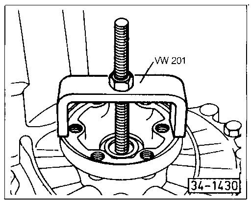
| 3. | Mount a press tool to the drive flange (Fig. 6-6). Screw the threaded rod into the axle shaft then turn the nut on tool clockwise to compress the spring behind the flange. |
| Fig. 6-6. | Drive flange being installed. Installation tool shown (VW 201) threads into shaft. |
|
| 4. | Remove the circlip and the spring washer. |
CAUTION-
The drive flange is under spring force and may release suddenly when the circlip is removed. Use extreme care when removing the circlip.
|
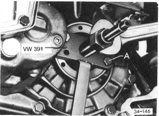
| 5. | Remove the drive flange from the transaxle. If necessary, use a puller as shown in Fig. 6-4. Inspect the flange and plan to replace it if there is a groove worn where it contacts the oil seal. |
CAUTION-
The internal threads of the shaft are used to reinstall the drive flange. Avoid thread damage during removal.
|
| Fig. 6-4. | Drive flange being removed. Puller VW 391 shown. Puller mounts to drive flange with M8 x 30 bolts (A). |
|
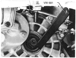
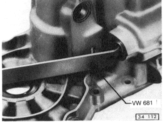
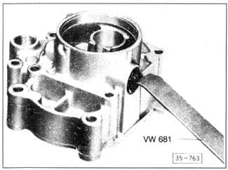
| 6. | Note the position of the seal, then pry the faulty seal from its recess using a hooked seal removal tool, as shown in Fig. 6-5, or a large screwdriver. |
| Fig. 6-5. | Drive flange oil seal being removed. Volkswagen special tool VW 681 shown. |
|
| 7. | Make sure the new seal has a spring behind its lip. Pack the open side of the new seal with multipurpose grease. Drive the new seal into place as originally installed. |
| 8. | Install the drive flange as shown in Fig. 6-6. |
| 9. | Install the spring washer, a new circlip, and a new dust cap. Attach the drive axle as described in SUSPENSION AND STEERING. |
To replace selector shaft oil seal:
| 1. | Shift the transmission into neutral. |
| 2. | Remove the selector shaft lever. Unscrew the nut holding the lever to the selector shaft, then disconnect the connecting link from the top of the selector shaft lever. (See the earlier Fig. 4-2.) |
| 3. | Pull the lever off the selector shaft, noting its position on the shaft. Remove the flexible boot and clean the exposed end of the selector shaft. |
| 4. | Remove the detent plunger (or bolt) from the top of the transaxle housing, then remove the 5th gear lockout plunger. See Figs. 6-1, 6-2, and 6-3 on the previous page. Remove the reverse/upshift light switch by removing the two mounting bolts. |
| 5. | Remove the clutch cable and rubber stop/guide from the transaxle as described in 5.1 Clutch Cable. |
| 6. | To gain access to the selector shaft, remove the selector shaft cover as shown in Fig. 6-7. Use care to avoid losing the spring as the cover is removed. Remove the selector shaft by hand-pressing it out through the cover opening. |
| Fig. 6-7. | Selector shaft cover being removed. Hex socket size is 27mm. Use short bolt (27mm head) and locknuts with wrench in place of special tool shown. |
|
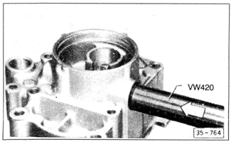
| 7. | Pry out the old seal, as shown in Fig. 6-8, and install a new seal. |
| Fig. 6-8. | Selector shaft oil seal being removed. |
|
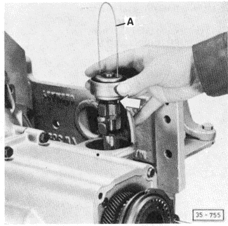
| 8. | Lubricate the new oil seal and all surfaces of the selector shaft with multipurpose grease, then carefully install the selector shaft in the transaxle case. See Fig. 6-9. |
| Fig. 6-9. | Selector shaft (arrow) being installed. Bent coat hanger wire or welding rod (A) can be inserted as shown to keep shaft components from moving while engaging shift forks. |
|
| 9. | The rest of the installation is the reverse of removal Torque the selector shaft cover to 50 Nm (37 ft. lb.). Adjust the selector shaft adjusters as described in 6.1 External Adjustments. Torque the selector shaft lever mounting nut to 15 Nm (11 ft. lb.). |
To replace clutch release shaft oil seal:
| 1. | Remove the clutch cable from the clutch release shaft as described in 5.1 Clutch Cable, then remove the stop clip from side of the release lever. Drain the transaxle as described in LUBRICATION AND MAINTENANCE. |
| 2. | Pierce the end cap and pry the cap out of its recess in the 5th gear/clutch release bearing housing. See Fig. 6-10. |
| Fig. 6-10. | Exploded view of clutch release mechanism. |

|
| 3. | Remove the circlip from each side of the clutch release shaft, then pull the clutch release shaft from the transaxle case. Remove clutch lever and the return spring. |
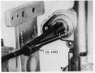
| 4. | Remove the oil seal as indicated in Fig. 6-11. Drive in a new oil seal as shown in Fig. 6-12. |
| Fig. 6-11. | Clutch release shaft oil seal being removed. |
|
| Fig. 6-12. | Clutch release shaft oil seal being installed. |
|
| 5. | Position the clutch lever and the return spring in the housing. The central hook of the return spring should lie atop the lug on the clutch lever, and the spring's end hooks should point downward so that the clutch lever is held away from the clutch release bearing. |
| 6. | Lightly coat the release bearing with multipurpose grease. Then lubricate the seal lip and pack the lubricant into the seal's open side. |
| 7. | Insert the clutch release shaft, being careful that the splines do not damage the oil seal, and engage its splines with the clutch lever. The splines will mate only one way. |
| 8. | Install the retaining circlips and check that the return spring is correctly tensioned when the operating lever is lifted to its normal operating position. |
| 9. | Install a new end cap as shown in Fig. 6-13. Use Volkswagen special tool no. VW 792/2 or equivalent to install the cap evenly. |
| Fig. 6-13. | New end cap being installed. |

|
| 10. | Install the stop clip and the clutch cable to the clutch release lever. If necessary, adjust the clutch pedal free-play as described in LUBRICATION AND MAINTENANCE. |
|