5.1 Clutch Cable
Two types of clutch cables are used on the vehicles covered by this manual. The more conventional, manually-adjusted cable needs periodic adjustment to compensate for the wear of the clutch friction material. For mileage intervals, see LUBRICATION AND MAINTENANCE.
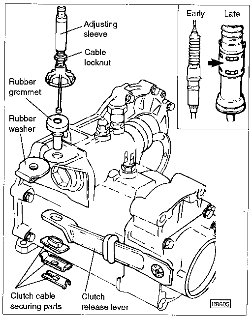
Some models are equipped with a self-adjusting clutch cable. It has a built-in mechanism which automatically compensates for wear, adjusting every time the clutch pedal is actuated. The self-adjusting cable can be identified by the rubber boot atop the clutch cable sleeve on the transaxle end of the cable, as shown in Fig. 5-2. The two cables are not interchangeable.
| Fig. 5-2. | Exploded view of clutch cable and related parts. Inset shows two versions of self-adjusting cable. Later version is identified by sheath (arrow). |

|
Removal and installation of the clutch cable can be accomplished without any special tools. Replacement self-adjusting cables come with a holding strap that relieves the spring tension and allows easy installation. If the cable does not have the strap attached, a helper may be needed during installation.
To replace clutch cable:
| 1. | On manually-adjusted cables, loosen the adjusting sleeve locknut and turn the sleeve clockwise until the cable's tension is relieved. Remove the securing parts from the cable end beneath the clutch release lever and pull the cable end from the lever. |
| 2. | On self-adjusting clutch cables, depress the clutch pedal several times. Compress the spring (under the rubber boot) and have a helper remove the securing parts from beneath the clutch release lever. Pull the cable end from the lever. |
CAUTION-
Do not open the automatic adjustment mechanism. If the adjustment mechanism is opened, the cable assembly will need to be replaced.
|
| 3. | Unhook the cable end from the top of the clutch pedal and pull the cable through the firewall from the engine compartment side. |
| 4. | Install the clutch cable. Lubricate both ends with multipurpose grease, then insert the clutch cable end through the firewall grommet and hook the cable onto the clutch pedal. |
| 5. | Position the rubber washer and the rubber grommet as shown in Fig. 5-3. |
| Fig. 5-3. | Rubber washer and rubber grommet correctly installed. Rubber washer 1 is fitted with lip 2 parallel to selector shaft cover 3 to protect vent. |

|
CAUTION-
The rubber parts must be installed correctly. If not, the transaxle vent which is protected by the washer may become clogged, and cause oil leakage past the seals.
|
| 6. | If reinstalling a used self-adjusting cable, compress the spring (beneath the rubber boot). |
| 7. | Insert the cable end through the rubber grommet and the release lever. Attach the securing parts to the end of the cable. |
| 8. | On self-adjusting cables, adjust clutch pedal freeplay by removing the spring retaining strap or relieving the spring tension, and then operating the clutch pedal several times. |
To adjust (except self-adjusting clutch cable):
| 1. | Operate the clutch pedal several times. Raise the clutch release lever by hand until resistance is felt. |
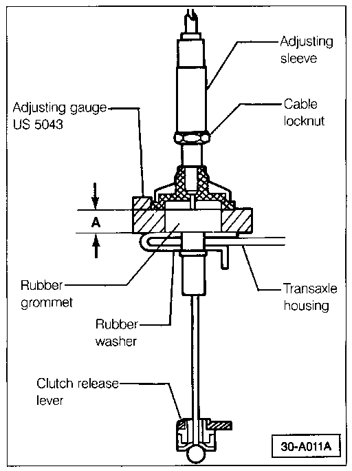
| 2. | Adjust freeplay by turning the adjusting sleeve counterclockwise, as shown in Fig. 5-4, until the clearance between the cable's large plastic flange and the transaxle housing is 12.0 mm (15/32 in.). |
| Fig. 5-4. | Adjusting clutch freeplay. Dimension A should be 12 mm (15/32 in.) while raising clutch release lever by hand. Adjusting gauge shown is Volkswagen special tool no. US 5043 (order no. TU5 043 000 30 ZEL). |

|
| 3. | Hold the adjusting sleeve and tighten the locknut against the sleeve. Freeplay at the clutch release lever should now be approximately 6 mm (1/4 in.). Torque the locknut to 4 to 6 Nm (36 to 48 in. lb.). |
|


