4.2 Radio and AntennaThe factory-installed radio is removed using two U-shaped clips inserted into the face plate of the radio at the corners. To remove the radio, disconnect the battery ground strap. Push the clips in until they click into position, and then withdraw the radio. Remove the clips before installing the radio, and make sure that the rubber mounting plug is properly engaged. Additional U-shaped clips are available separately from an authorized Volkswagen dealer, tool no. VW 160 (order no. TV0 160 000 90 ZEL).
Factory or after-market radios can be installed on models with or without the factory-installed prep kit. Disconnect the battery ground strap. All wiring for installing a radio is accessible after removing the radio face plate and instrument panel trim plate as described in 4.1 Instrument Cluster and Instrument Panel. See the wiring diagrams in ELECTRICAL SYSTEM marked Radio, or Stereo Radio to help identify connectors, or to find a power source and ground.

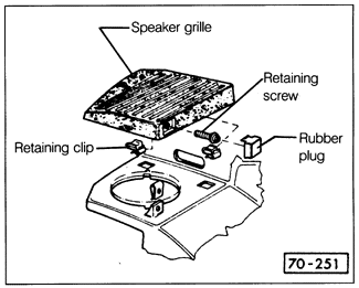
Speakers can be installed in the instrument panel in all cars, in the rear hat shelf on Jettas, and in the hat shelf extension on Golf and GTI models. See Fig. 4-10 above when removing the front speaker grilles. To replace the roof-mounted antenna on 16-valve models, the radio must be removed, and the headliner must be removed as described in 4.9 Headliner. To replace a fender-mounted antenna, remove the instrument cluster as described in 4.1 Instrument Cluster and Instrument Panel, and remove the wheel house liner as described in 6.4 Trim, Bumpers, and Body. Working from the engine compartment, remove the plenum drip tray and pull the antenna cable and its grommet out of the firewall. Note the cable routing in the foam tube behind the instrument cluster, and reinstall the same way, to make sure that it does not crimp any vacuum hoses after installation. Remove the antenna retaining nut at the base of the antenna, pull the antenna down into the wheelhouse, and remove it from the mounting bracket. When installing the antenna, use multi-purpose grease on the mounting hole and the nut to reduce rusting. If the antenna is not to be reinstalled, a plug is available to seal the fender hole (part no. 321 821 169) and to seal the hole in the firewall (part no. N 020 027 1) be sure to also plug the hole in the plenum tray. |