4.1 Instrument Cluster and Instrument Panel
The instrument cluster can be removed without removing the instrument panel, however, the instrument cluster must be removed to remove the instrument panel.
To remove the instrument cluster:
| 1. | Disconnect the negative (-) terminal from the battery. |
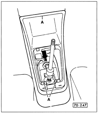
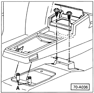
| 2. | Remove the center console. On manual transmission cars first remove the gearshift lever knob and the gear-shift boot. On automatic transmission cars remove the selector lever cover plate. Finally, depending on the center console as shown in Fig. 4-1 and Fig. 4-2, remove the retaining screws and partially remove the console. Separate any electrical connectors from behind. |
| Fig. 4-1. | First type of center console showing screw (arrow) to be removed. Additional screws may be located behind ash tray. Pull console back from retaining guides A and up. |
|
| Fig. 4-2. | Second type of center console showing screws to be removed. Pull console up off retaining guides A. |
|
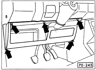
| 3. | Remove the lower-left instrument panel tray by removing the screws indicated in Fig. 4-3. On some Golf and GTI models the tray may run the full length of the instrument panel, or on models with passive restraint there may be a knee bar. With full-length trays it is necessary to remove two screws securing the fuse panel to the tray. Kneebars are held with two bolts at either end. |
| Fig. 4-3. | Retaining screws (arrows) to be removed from left-side instrument panel tray. |
|
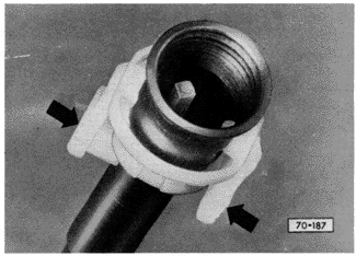
| 4. | Remove the speedometer cable. Reach behind the instrument cluster and pinch the cable retaining clip, sliding it off the cable end. See Fig. 4-4. Pull the cable from the cluster. |
| Fig. 4-4. | Speedometer cable retaining clip. Arrows indicate clips to be pinched. |
|
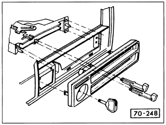
| 6. | Remove the heating and ventilation control head from the instrument panel. Pull the control levers straight out, unclip the trim plate, disconnect the wires to it, and remove the plate. Then remove the three control head mounting screws. See Fig. 4-5. |
| Fig. 4-5. | Exploded view of ventilation control head showing removal of control levers. |
|
| 7. | Remove the radio, if applicable. |
| 8. | On Jettas, pry the electrical switches from the center of the instrument panel trim plate and remove the switches by disconnecting the electrical connectors. |
| 9. | On Golf and GTI models, remove the headlight switch. |
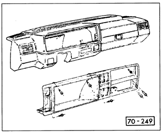
| 10. | Remove the instrument panel trim plate. On Golf and GTI models, the plate is held in place by ten spring clips. Work around the rim of trim plate, gently freeing each clip. On Jettas, the plate is held in place by the retaining screws shown in Fig. 4-6. |
| Fig. 4-6. | Retaining screws to be removed from instrument panel trim plate on Jettas. |
|
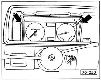
| 11. | Remove the two instrument cluster retaining screws indicated in Fig. 4-7 and partially remove the cluster. On Golf and GTI models, the right screw is behind one of the blank switch covers. |
| Fig. 4-7. | Retaining screws (arrows) to be removed from instrument cluster. |
|
| 12. | Working from the rear, disconnect all electrical and vacuum connections, and label the vacuum lines. Remove the instrument cluster. |
Installation is the reverse of removal.
To remove instrument panel:
| 1. | Remove the instrument cluster as described above. |
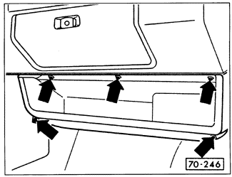
| 2. | Remove the right-side lower instrument panel tray where applicable by removing the screws shown in Fig. 4-8. |
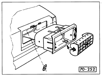
| 3. | Pry out the left, center, and right ventilation grilles from their housings as shown in Fig. 4-9, then remove the retaining screws and the housings |
| Fig. 4-8. | Retaining screws (arrows) to be removed from right-lower instrument panel tray. |
|
| Fig. 4-9. | Ventilation grille and related parts. |
|
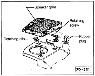
| 4. | Remove the speaker grilles and, if applicable, the speakers. Remove the grille retaining screw and slide the grille toward the rear of the car. See Fig. 4-10. On Golfs and GTIs, the screw is covered by a full-length trim piece. |
| Fig. 4-10. | Exploded view of speaker grille mounting hardware. Jetta grille is shown, Golf and GTI are similar. |
|
| 6. | On Golf and GTI models, remove the electrical switches from the center of the instrument panel. Remove the nuts holding the switch bracket in place and disconnect all electrical connectors. |
| 7. | On Golf and GTI models, remove the relay panel from its bracket underneath the left side of the instrument panel, and disconnect all electrical connections from the left side of the instrument panel. |
| 8. | Pry out the glove box light assembly and remove its wiring connector. Remove the glove box by removing the screws around its rim. |
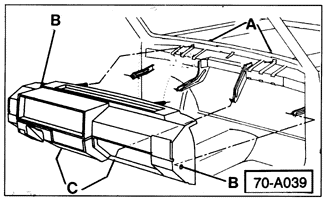
| 9. | Remove the drip tray from the base of the windshield in the engine compartment, then remove the screws and nuts shown in Fig. 4-11. Partially pull the instrument panel away from the body. Remove any other electrical connections to the panel, and then pull it from the vehicle. |
| Fig. 4-11. | Location of instrument panel padding retaining screws B, C and nuts A to be removed. Nuts are in air plenum in engine compartment. |
|
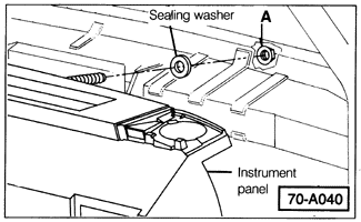
Installation is the reverse of removal. Make sure that the sealing washers on the instrument panel studs are in place as shown in Fig. 4-12 before the panel is installed, and double check all electrical connections.
| Fig. 4-12. | Sealing washer installation for instrument panel studs. Stud nut is at A. |
|
|


