Admin
Создатель сайта
Команда форума
- Сообщения
- 11 123
- Реакции
- 4 343
- Город
- Россия, Москва
- Авто
- VW Tiguan 2.0 DBGC 2018, VW Touran 1.6 BSE 2008
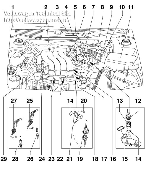
Расположение компонентов:

1 - Activated charcoal filter solenoid valve 1 -N80-
2 - Intake manifold
3 - 52-pin connector. Only disconnect with ignition switched off.
4 - Engine control unit (Motronic control unit -J220-)
5 - 28-pin connector. Only disconnect with ignition switched off.
6 - Throttle valve control module -J338-. On replacement, the control unit must be adapted to the electronic immobilizer
7 - Heater element -N79-
8 - Secondary air inlet valve -N112-
9 - Secondary air pump relay -J229-
10 - Air mass meter -G70- with intake air temperature sender -G42-
11 - Air cleaner
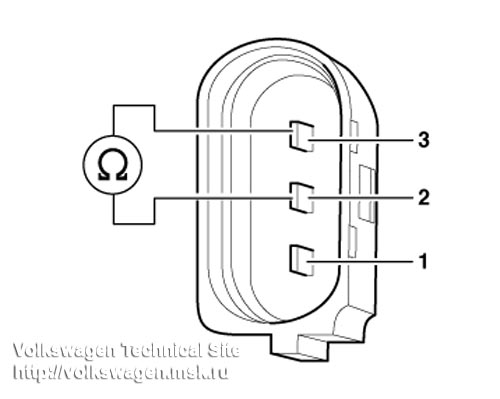
12 - 4-pin connector
Wiring chamber 1 and wiring chamber 3 for -G62-.
Contacts 1 and 3 are gold-plated.
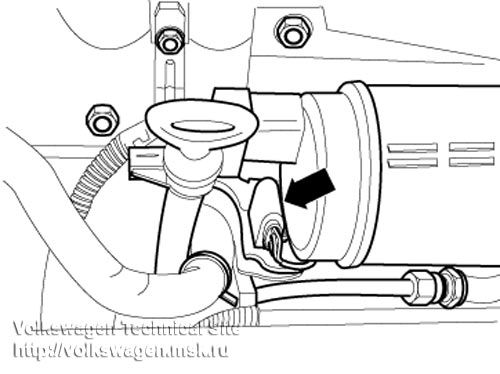
13 - Coolant temperature sender -G62-
For engine control unit.
With coolant temperature gauge sender -G2-
If necessary, release pressure in cooling system before removing.
Wiring chamber 1 and wiring chamber 3 for -G62-.
Contacts 1 and 3 are gold-plated.
14 - Sealing ring. Renew if damaged.
15 - Securing clip
16 - Injectors -N30-, -N31-, -N32-, -N33-
17 - Ignition coils (-N-, -N12 With output stage -N122-.
18 - Secondary air pump motor -V101-
19 - 3-pin connector
Grey for engine speed sender -G28-.
20 - 10 Nm
21 - Engine speed sender -G28-
22 - Knock sensor 2 -G66- Brown connector.
23 - Knock sensor 1 -G61- Black connector.
24 - Fuel pressure regulator
25 - 4-pin connector Black.
For lambda probe 1 before catalytic converter -G39- and lambda probe heating -Z19-.
On right under vehicle.
26 - Lambda probe 1 before catalytic converter -G39-, 50 Nm
On exhaust manifold.
When renewing erase fault memory
27 - 4-pin connector Colour brown
For lambda probe 2 after catalytic converter -G130- and lambda probe heating -Z29-.
Right on underside of vehicle.
28 - Lambda probe 2 after catalytic converter -G130-, 50 Nm
On rear of catalytic converter.
When renewing erase fault memory
29 - Hall sender -G40-
1 - Activated charcoal filter solenoid valve 1 -N80-
2 - Intake manifold
3 - 52-pin connector. Only disconnect with ignition switched off.
4 - Engine control unit (Motronic control unit -J220-)
5 - 28-pin connector. Only disconnect with ignition switched off.
6 - Throttle valve control module -J338-. On replacement, the control unit must be adapted to the electronic immobilizer
7 - Heater element -N79-
8 - Secondary air inlet valve -N112-
9 - Secondary air pump relay -J229-
10 - Air mass meter -G70- with intake air temperature sender -G42-
11 - Air cleaner
12 - 4-pin connector
Wiring chamber 1 and wiring chamber 3 for -G62-.
Contacts 1 and 3 are gold-plated.
13 - Coolant temperature sender -G62-
For engine control unit.
With coolant temperature gauge sender -G2-
If necessary, release pressure in cooling system before removing.
Wiring chamber 1 and wiring chamber 3 for -G62-.
Contacts 1 and 3 are gold-plated.
14 - Sealing ring. Renew if damaged.
15 - Securing clip
16 - Injectors -N30-, -N31-, -N32-, -N33-
17 - Ignition coils (-N-, -N12
With output stage -N122-. 18 - Secondary air pump motor -V101-
19 - 3-pin connector
Grey for engine speed sender -G28-.
20 - 10 Nm
21 - Engine speed sender -G28-
22 - Knock sensor 2 -G66- Brown connector.
23 - Knock sensor 1 -G61- Black connector.
24 - Fuel pressure regulator
25 - 4-pin connector Black.
For lambda probe 1 before catalytic converter -G39- and lambda probe heating -Z19-.
On right under vehicle.
26 - Lambda probe 1 before catalytic converter -G39-, 50 Nm
On exhaust manifold.
When renewing erase fault memory
27 - 4-pin connector Colour brown
For lambda probe 2 after catalytic converter -G130- and lambda probe heating -Z29-.
Right on underside of vehicle.
28 - Lambda probe 2 after catalytic converter -G130-, 50 Nm
On rear of catalytic converter.
When renewing erase fault memory
29 - Hall sender -G40-