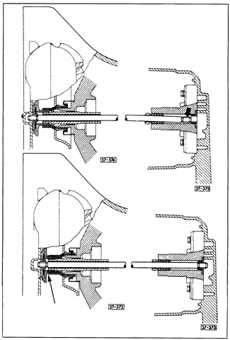
InstallingEngine and transaxle installation is the reverse of removal. On models with automatic transmission, make certain during reassembly that the torque converter has not slipped from its support. See Fig. 5-13.

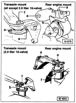
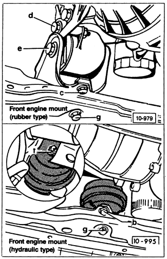
The engine-to-transaxle bolts are two sizes, 10 mm and 12 mm. On all engines except the 2.0 liter 16-valve, torque the larger (12 mm) bolts to 80 Nm (59 ft. lb.) and the smaller (10 mm) bolts to 45 Nm (33 ft. lb.). On the 2.0 liter 16-valve engine, torque 12 mm bolts to 55 Nm (41 ft. lb.) and 10 mm bolts to 45 Nm (33 ft. lb.). On models with automatic transmission, torque the bolts holding the engine drive plate to the torque converter to 30 Nm (22 ft. lb.). Torque starter mounting bolts to 25 Nm (18 ft. lb.). On all models, torque the cover plate mounting bolts to 15 Nm (11 ft. lb.). With the engine and transaxle in position, install the rear engine mount first, then install the transaxle mount. Roughly align the engine and transaxle on these mounts, and then install the remaining mounts. The mounting bolts and nuts and their torque values are identified in Fig. 5-14 and Fig. 5-15. Following installation of the remaining engine and transaxle parts and fluids, the assembly should be aligned in its mounts as described in Aligning Engine and Transaxle Assembly.


|