Fuel DistributorThe fuel distributor's control plunger, moving up or down in its bore, varies the openings of the metering ports-one for each injector. The differential pressure regulator, operated electrically by the control unit, adjusts pressure in the lower chambers. Lower chamber pressure in turn controls the pressure differential at the metering ports. It is this pressure differential which determines how much fuel is delivered by the injectors. Fig. 6-14 is a cross-section of the fuel distributor showing the control plunger, a metering port, the upper and lower chambers, and the differential pressure regulator. The fuel distributor is a factory-calibrated unit that does not normally require service or cause problems. It is, however, a precision device that may be adversely affected by deposits or corrosion from contaminated fuel. For fuel filter maintenance information, see LUBRICATION AND MAINTENANCE.

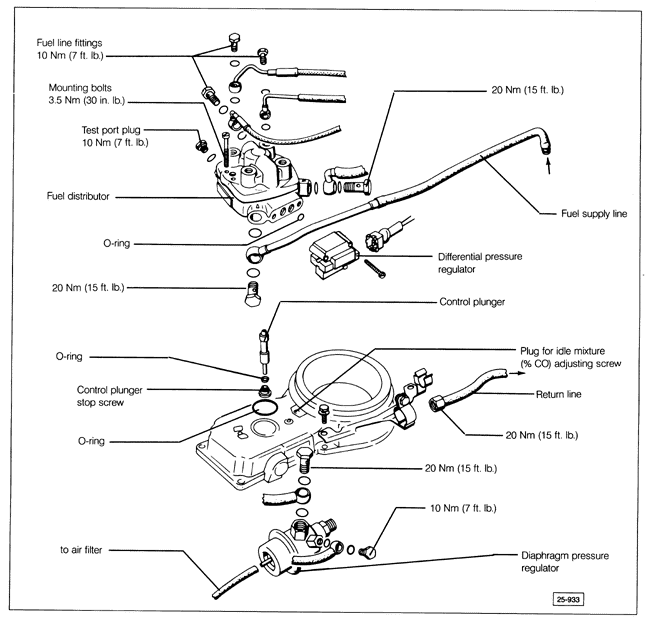
On some cars, a mini-filter is installed during manufacture in the fuel inlet bolt at the fuel distributor. This filter should be removed and a normal banjo fitting bolt installed in its place at a specified interval. For more information on identifying and replacing the mini-filter, see LUBRICATION AND MAINTENANCE. If uniform distribution of fuel to the injectors is in doubt, the fuel distributor can be checked by measuring and comparing injector fuel delivery, as described in 4.7 Fuel Injectors (CIS, CIS-E, and CIS-E Motronic). Fig. 6-15 is an exploded view of the fuel distributor showing fuel line connections and mounting detail. After any disassembly or adjustment of the fuel distributor or the air flow sensor, idle mixture (% CO) must be adjusted. See 6.7 Idle Specifications. Before making the adjustments, make sure the air flow sensor plate position is correct as described above in Basic Adjustments.

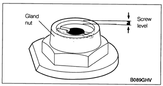
If air flow sensor plate free play is incorrect as described earlier under Basic Adjustments, an adjustment to the air control plunger stop screw is required. The procedure is described later under this heading. To remove and clean the control plunger, remove the two small mounting screws from the top of the fuel distributor and pull the fuel distributor up off the air flow sensor housing. To avoid having to adjust the stop screw when reassembling, mark the position of the screw on the gland nut and measure the depth of the screw as shown in Fig. 6-16. Then remove the stop screw and the seal and remove the control plunger. Inspect the seal. It should be replaced if it is deformed or otherwise damaged. Clean the plunger with carburetor cleaner or some equivalent, then lubricate the plunger with fuel and reinstall it. Install the seal with the smaller diameter side facing the control plunger. Install the stop screw and adjust to its previously noted position or make the control plunger basic adjustment as described below.
To check the control plunger stop screw basic adjustment, measure the distance from the gland nut to the stop screw as shown in Fig. 6-16. It should be approximately 0.6 mm (0.024 in.). If not, adjust it to this height by turning the stop screw. Turning the screw in (clockwise) will increase free play; turning the screw out (counterclockwise) will reduce free play.

|