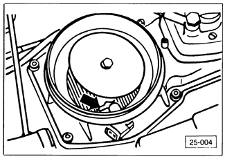
Basic AdjustmentsThe sensor plate should be located in the center of the air cone, as shown in Fig. 6-7. If the plate is off-center, or if it contacts the air cone, it should be adjusted. Remove the bolt in the center of the sensor plate, apply thread locking compound to the bolt, and reinstall it, centering the plate before tightening the bolt.

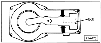
If the plate cannot be centered as described above, adjust the position of the sensor plate lever on its shaft. Separate the air flow sensor housing from the air filter housing, and remove the clamp bolt from the end of the air flow sensor lever as indicated in Fig. 6-8. Coat the bolt threads with thread locking compound and reinstall the bolt hand-tight. Center the air flow sensor lever on the shaft and tighten the clamping bolt, then repeat the sensor plate adjustment.

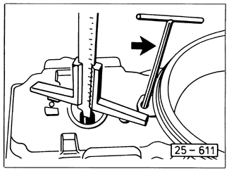
If the sensor plate is hard to move or moves with uneven resistance, clean and lubricate the sensor plate lever pivot so that it moves smoothly. If there is resistance caused by a binding control plunger, remove and clean the control plunger as described below in Fuel Distributor. At rest, the edge of the sensor plate should be 1.9 mm (.075 in.) below the top edge of the narrowest part of the air cone, as shown in Fig. 6-9.
For all CIS-E engines (not including CIS-E Motronic), sensor plate rest position up to 2.1 mm (.083 in.) below the edge is acceptable. Adjust the rest position of the plate by bending the wire spring stop under the plate, as indicated in Fig. 6-10. For CIS-E Motronic, a sensor plate rest position up to 3.0 mm (.118 in.) below the edge is acceptable. Adjust the rest position of the plate from underneath the air flow sensor housing using the adjusting screw shown in Fig. 6-11.
When the engine is not running, there should be a small gap between the sensor lever and the fuel distributor's control plunger, as shown in Fig. 6-12. This gap ensures that the control plunger seats against the O-ring at the bottom of its bore. The plunger seats on the O-ring to help maintain fuel pressure at the injectors, thus helping prevent fuel vaporization and hard starting. To check the gap, the engine should be at normal operating temperature. Actuate the starter for a few seconds to run the fuel pump and ensure that the fuel system is pressurized. Slowly lift the air flow sensor plate. There should be a small amount of free play, then some resistance. The free play, measured at the edge of the sensor plate, should be just enough to allow the sensor plate to rise and be even with the top edge of the narrowest part of the air cone. To adjust this free play, the fuel distributor must be removed from the air flow sensor housing. The adjustment is described later in this section under Fuel Distributor. If either the air flow sensor or fuel distributor is disassembled or replaced, a basic adjustment of the air flow sensor lever may be required. To check the air flow sensor lever basic adjustment, measure the distance from the fuel distributor mounting surface to the sensor plate lever roller with the sensor plate at rest, as shown in Fig. 6-13. On CIS-E systems, this distance should be 19.0 ± 0.1 mm (0.75 ± 0.004 in.). On CIS-E Motronic systems, the distance should be 18.8 ± 0.1 mm (0.74 ± 0.004 in.). To adjust, remove the tamper-proof plug in the top of the air flow sensor housing and turn the idle mixture adjusting screw, using a 3 mm hex wrench.
Some cars are equipped with a protective screen atop the air flow sensor inside the intake air boot. When reinstalling the rubber intake air boot, use care not to damage or distort the screen. A damaged screen may limit sensor plate travel.


|