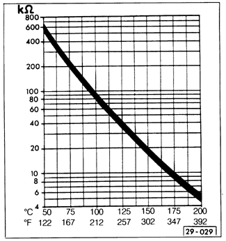
Testing EGR System (California models only)The EGR valve should open only under part-throttle vacuum. A rough idle may indicate that the valve is incorrectly opening at idle. Also, on California models with engine code 9A (2.0 liter 16-valve) the EGR system is monitored by the CIS-E Motronic control unit. The temperature in the intake manifold is measured by the intake temperature sensor as an indication of EGR function. Problems with the temperature sensor or the EGR system are stored in the fault memory of the CIS-E Motronic control unit. Always begin troubleshooting by reading out the fault codes as described in FUEL SYSTEM-GASOLINE. The codes will help determine which component of the system needs to be tested. If the fault code indicates a problem, test the temperature sensor's resistance and the continuity of the wiring from the sensor to the Motronic control unit connector as described in FUEL SYSTEM-GASOLINE. Fig. 6-3 gives the correct sensor resistance values based on ambient air temperature. Replace the sensor if its resistance is incorrect, or repair breaks in the wiring as necessary.

Test the EGR valve with the engine oil temperature at 122°F (50°C) or higher. Make sure there are no leaks at the vacuum line connections and that the lines are not plugged or kinked. To check the valve, start the engine and let it idle. Remove the vacuum line from the EGR valve to the thermo-pneumatic valve at the thermo-pneumatic valve. See Fig. 6-4. When vacuum is applied to the disconnected end of the line, the idle speed should become erratic. If it does not, remove the EGR valve and check for blockages in the holes in the exhaust and intake manifolds and in the EGR pipe, and clean them out. If there are no blockages, replace the EGR valve.
To test the thermo-pneumatic valve, locate the two vacuum lines leading from the valve to EGR valve and the vacuum amplifier. Disconnect these lines from the EGR valve and the vacuum amplifier and blow through one of them. Below an engine coolant temperature of 81°F (27°C) there should be no flow through the thermo-pneumatic valve. Above a coolant temperature of 120°F (49°C) air should flow through the valve. If air flow is incorrect, first check for damaged or blocked vacuum lines. If the lines are clear, replace the thermo-pneumatic valve. Use a new sealing washer and use sealing compound on the valve's threads. Some engine coolant may leak out when the valve is removed. If so, check and correct the coolant level as described in LUBRICATION AND MAINTENANCE.

Test the vacuum amplifier using a vacuum gauge. Start the engine and let it idle. With the gauge connected in line between the throttle body and vacuum amplifier (the red vacuum line in Fig. 6-4, above), the gauge should read at least 10 mbar (.2992 in.Hg.). Next connect the gauge in line between the thermo-pneumatic valve and the vacuum amplifier (the blue vacuum line in Fig. 6-4, above). The gauge should now read 65 to 120 mbar (1.945 to 3.590 in.Hg.). If readings are incorrect, first check for damaged or blocked vacuum lines. If the lines are clear, replace the vacuum amplifier. |