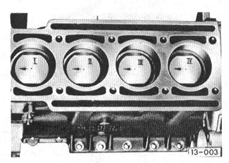
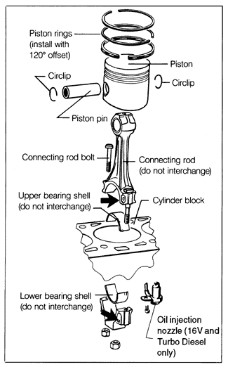
Pistons and Connecting RodsPistons, piston pins, piston rings, connecting rods, and bearings, if they are to be reused, should never be interchanged. Mark the cylinder numbers on connecting rods and connecting rod caps before removal. Mark the piston tops as shown in Fig. 6-3 (avoid scratching the piston). Components of one piston and connecting rod assembly are shown in Fig. 6-4.


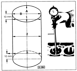
The piston pin should fit such that, with the piston heated to approximately 60°C (140°F) in an oil bath, a light push will move the pin. Replace the piston and the pin if the fit is excessively loose. Connecting rods should always be replaced in complete sets. Measure cylinder bores at approximately the top, the middle, and the bottom of piston travel, and at right angles (90°), as shown in Fig. 6-5. The top and bottom measurements should be made approximately 10 mm (3/8 in.) from the ends of the cylinder. Nominal piston and cylinder bore diameter specifications are given in Table K. Nominal piston diameters are also marked on the piston crowns.

Table k. Cylinder and Piston Diameter Specifications
Maximum out-of-round variation in any one cylinder is 0.04 mm (.0016 in.). Minor irregularities may be corrected by honing. If the diameter of any one cylinder exceeds the nominal dimension by more than 0.08 mm (.003 in.), all four cylinders should be rebored and honed to accept new oversized pistons. Visually inspect the bores for scoring and other imperfections which will also prevent good piston ring to cylinder wall sealing. When fitting pistons, the piston-to-cylinder clearance should be 0.03 mm (.0012 in.). Maximum allowable piston-to-cylinder clearance is 0.07 mm (.0028 in.). Measure connecting rod bearing clearances using Plastigage®. Inspect the connecting rods for any bending, distortion, or other visual damage. Connecting rod specifications are listed in Table l. Table l. Connecting Rod Specifications
If connecting rod radial clearance is excessive, the crankshaft connecting rod journals should be checked as described in Crankshaft and Intermediate Shaft. If the crankshaft journal diameters are within specifications, recheck radial clearance using new bearing shells. When installing each connecting rod to the crankshaft, the two bearing shells' retaining tabs should be on the same side of the journal, and the marks on the connecting rods, shown earlier in Fig. 6-4, should face the drivebelt side of the engine. |

