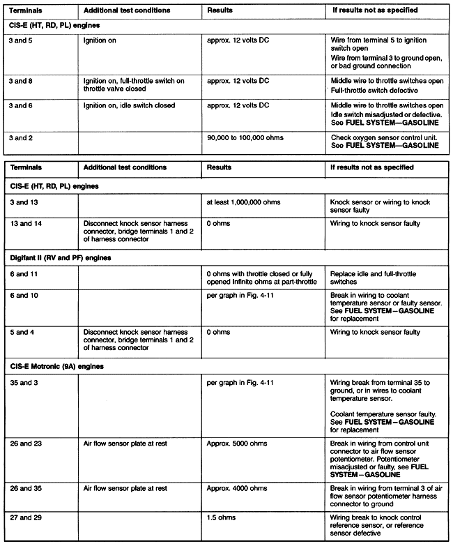
4.6 Troubleshooting Knock Sensor SystemIf the knock sensor resistance and mounting bolt torque are correct, this heading outlines the final steps for troubleshooting faults in the knock sensor system. The sequence of the test steps is important. Follow the test sequence as it is presented in order to logically isolate the faulty wire or component. With the ignition off, disconnect the harness connector from the knock sensor control unit, Digifant control unit, or Motronic control unit. The knock sensor control unit is mounted in the cowl behind the firewall on the right (passenger) side of the car. The Digifant or Motronic control unit is mounted in the cowl behind the firewall on the left (driver's) side of the car. Using a multimeter, test for voltage or resistance at the terminals of the control unit connector according to Table j. To prevent damage to sensitive electronic components, make connections with the ignition off, and leave the ignition off unless otherwise specified. In most cases, these tests check both the wiring and the component at the same time. If the results are not as specified, the table lists probable causes and further checks.
Table j. Knock Sensor System Wiring Tests
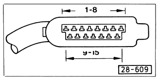
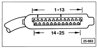
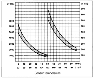
Fig. 4-9 identifies the terminals of the knock sensor control unit connector for HT, RD, and PL engines. Fig. 4-10 identifies the terminals of the Digifant control unit connector for RV and PF engines. Fig. 4-11 gives the resistance values for the Digifant or Motronic coolant temperature sensor. If the all of the wiring and component checks are correct, also check the wiring to the Hall sender, ignition control unit, or coil power stage for intermittent wiring breaks, using the appropriate current flow diagrams in ELECTRICAL SYSTEM as a guide. If there are no breaks there, then the control unit is most likely faulty.


|
