Removing and Installing Injection Pump
To remove:
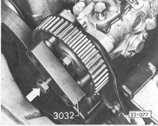
| 2. | Loosen the injection pump sprocket retaining nut, but do not completely remove it. Using a puller, as shown in Fig. 5-14, apply tension to the sprocket. Lightly tap the puller bolt until the sprocket pops loose from the tapered shaft. Remove the puller, the nut and washer, and the sprocket. |
| Fig. 5-14. | Puller installed on fuel injection pump sprocket. Tension puller and tap bolt (arrow) to remove sprocket. Spacer between nut and puller screw prevents damage to pump shaft. |
|
| 3. | Disconnect the battery negative (-) terminal from the battery. |
| 4. | Detach all fuel pipes and hoses from the injection pump, including the fuel intake line from the fuel filter, and the fuel return line. Remove the fuel pipes to the injectors as a unit, taking care not to bend them. Cover the unions with a clean, lint-free cloth. |
WARNING-
Fuel will be expelled when the fuel lines are loosened. Do not smoke or work near heaters or other fire hazards. Have a fire extinguisher handy.
|
CAUTION-
Thoroughly clean all unions before disconnecting fuel lines.
|
| 5. | On turbo diesels, remove the bolt and hose at the top of the boost pressure enrichment housing leading from the housing to the intake manifold. |
| 6. | Disconnect the electrical wire from the stop solenoid. On the cars with an upshift indicator, disconnect the wires attached to the idle and full throttle switches. |
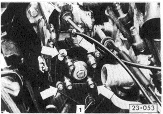
| 8. | Remove the bolt from the injection pump rear support (Fig. 5-15). Remove the bolts from the front injection pump mounting plate and remove the pump. |
| Fig. 5-15. | Injection pump rear support bolt (1). To avoid damage to the distributor plunger, do not loosen the bolts (arrows) on the fuel distributor head. |
|
To install:
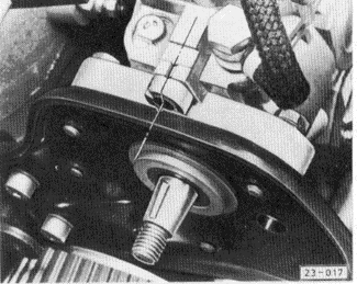
| 1. | Install the pump on the front and rear mounting plates, and loosely tighten the bolts. Align the marks indicated in Fig. 5-16, then torque the bolts to 25 Nm (18 ft. lb.). |
| Fig. 5-16. | Mark on fuel injection pump aligned with mark on mounting plate (broken line). |
|
| 2. | Reconnect the fuel lines and the fuel pipes to the injectors. Torque the connections to 25 Nm (18 ft. lb.). |
NOTE-
The fuel return line connection is labeled OUT. On normally-aspirated diesels, the return line connection is on the pump housing. On turbo diesels, the return line connection is on the boost pressure enrichment housing. Do not interchange the fuel supply union bolt with the return line union bolt.
|
NOTE-
The injector line connections on the pump are marked A,B,C,D. Connect No. 1 cylinder to A, No. 3 to B, No. 4 to C, and No. 2 to D. In reconnecting the fuel hoses, take care not to interchange the fuel supply union bolt with the return line union bolt, which is marked OUT on its head and contains a restrictor.
|
| 3. | On turbo diesels, reconnect the hose leading from the intake manifold to the boost pressure enrichment housing and torque it to 10 Nm (89 in. lb.). |
| 4. | Reconnect the electrical wires to the stop solenoid, and upshift sensors where applicable. Reconnect the accelerator cable and the cold start cable as described in 5.2 Accelerator Cable and 5.3 Cold Start System. |
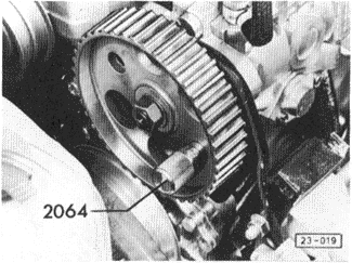
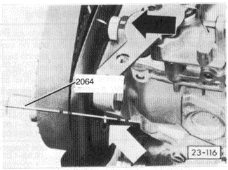
| Fig. 5-12. | Injection pump sprocket locked in position with pin. Volkswagen special tool no. 2064 (order no. T02 064 000 00 ZEL) shown. Snug fit is required, allowing no movement. |
|
| 5. | Position the injection pump sprocket on the shaft and loosely install the nut. Hand-turn the sprocket until it lines up with the mounting plate and the pump body as shown in Fig. 5-17. Lock the sprocket in position as shown in Fig. 5-12 above, and torque the nut to 45 Nm (33 ft. lb.). |
| Fig. 5-17. | Mark on injection pump sprocket aligned with mark on mounting plate and pump (black arrow). Installation of locking pin (white arrow) also shown. |
|
|


