Checking and Adjusting Injection Pump Timing
Precise injection timing is critical, since it also determines when combustion begins. Checking and adjustment of injection timing is necessary any time the injection pump or the timing belt have been loosened or replaced, and may be necessary at other times to maintain precise timing.
Injection timing is checked by measuring the injection pump plunger's stroke at TDC with a dial indicator. Adjustment, if necessary, is based on this measurement. Before adjusting injection pump timing, the cold start cable must be all the way in, and the camshaft drive belt must be properly installed and tensioned. See 5.4 Camshaft/Injection Pump Drive Belt.
To check and adjust:
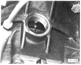
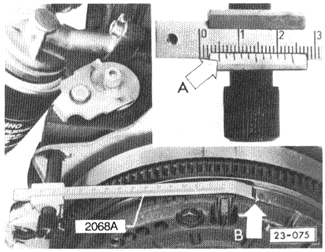
| 1. | Using a socket on the front crankshaft bolt, hand-turn the engine clockwise until No. 1 cylinder is at TDC. Both valves should be closed and the TDC mark on the flywheel should be aligned, as shown in Fig. 5-18 if the engine is installed and in Fig. 5-19 if it is not installed. |
| Fig. 5-18. | TDC mark on flywheel aligned with pointer in hole in bellhousing (engine installed). |
|
| Fig. 5-19. | Volkswagen special tool no. 2068A (order no. T02 068 A00 23 ZEL) being used to align TDC mark on flywheel (B) with engine removed. Use left notch (A) as measurement point. TDC is indicated when scale reads 5 mm for vehicles with manual transmission; 85 mm for vehicles with automatic transmission. |
|
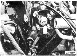
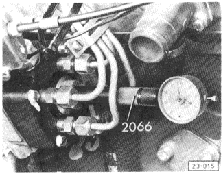
| 2. | Remove the timing-check plug from the pump cover, shown in Fig. 5-20, and install a dial indicator with (3 mm range) as shown in Fig. 5-21. The gauge should be installed so that it indicates about 2.5 mm (preload). |
WARNING-
Fuel will be expelled when the timing plug is removed. Do not smoke or work near heaters or other fire hazards. Have a fire extinguisher handy.
|
| Fig. 5-20. | Timing check plug (white arrow) to be removed for installation of dial indicator. Only the small central plug and its gasket should be removed. The black arrows indicate the fuel injection pump check valves. |
|
| Fig. 5-21. | Dial indicator mounted on fuel injection pump. Adapter shown is Volkswagen special tool no. 2066 (order no. T02 066 000 00 ZEL). |
|
| 3. | Hand-turn the crankshaft counterclockwise (opposite normal engine rotation) until the dial indicator stops moving. Zero the dial indicator. |
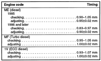
| 4. | Hand-turn the crankshaft clockwise (normal rotation), stopping precisely at TDC. With the engine at TDC, the dial indicator should read within the checking limits given in Table b. |
| 5. | If the dial indicator reading is within the checking values given, it is not necessary to adjust the injection timing. |
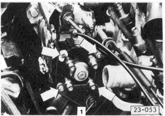
| Fig. 5-15. | Injection pump rear support bolt (1). To avoid damage to the distributor plunger, do not loosen the bolts (arrows) on the fuel distributor head. |
|
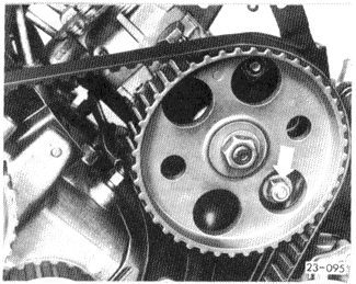
| 6. | If the dial indicator reading is out of specification, a timing adjustment is necessary. With the engine at TDC, slightly loosen the injection pump rear support bolt, shown earlier in Fig. 5-15, and the front mounting plate bolts as shown in Fig. 5-22. Rotate the pump, either clockwise or counterclockwise, until the dial indicator reading is within the adjusting specification tolerance. |
Table b. Injection Pump Timing
| Fig. 5-22. | Lower mounting plate bolt (arrow) accessible through hole in the injection pump sprocket. |
|
| 7. | Tighten the mounting bolts and torque them to 25 Nm (18 ft. lb.). Rotate the engine by hand through two complete revolutions (clockwise), and then repeat the checking procedure. Repeat the timing adjustment if necessary. |
| 8. | Remove the dial indicator. Reinstall the timing check plug with a new gasket, and torque it to 15 Nm (11 ft. lb.). |
| 9. | Start the engine and check for leaks around the timing check plug. If any is seen, the timing check plug may be retorqued to 25 Nm (18 ft. lb.). |
|


