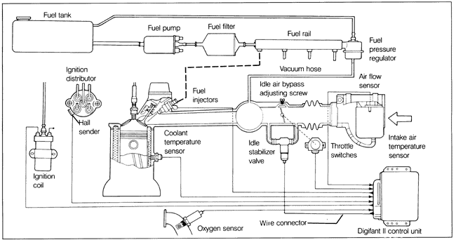
7. Digifant II Fuel InjectionFig. 7-1 shows the main components of the Digifant II engine management system. The Digifant II system combines the engine's ignition and fuel injection functions into one system, managed by a single electronic control unit. In the Digifant II system, basic fuel metering is determined by engine rpm and by the volume and temperature of the air entering the engine. The Digifant II control unit receives air flow volume and temperature data from the air flow sensor and engine rpm data from the ignition distributor, and distributes fuel to the engine through electrically-operated solenoid valve fuel injectors. Four injectors, one for each cylinder, are triggered simultaneously at a rate that is proportional to engine rpm. Fuel mixture is controlled by the length of the electrical impulse from the control unit-the length of time that the injectors are open. The injectors are mounted to a common fuel supply-called the fuel rail. Fuel pressure is regulated by a fuel pressure regulator mounted to the end of the fuel rail. Information on fuel injectors is found in this section under 4.8 Fuel Injectors (Digifant II). The fuel pressure regulator is covered separately under 4.4 Fuel Pressure Regulator. The Digifant II control unit makes additional adjustments to the amount of fuel delivered by the injectors based on input from various sensors. The oxygen sensor system provides the control unit with information on engine combustion efficiency by measuring the amount of oxygen in the exhaust stream. Switches on the throttle valve inform the control unit when the throttle is fully open or fully closed (at idle). A coolant temperature sensor, located on the engine cylinder head, provides the control unit with engine temperature information for adjustments during starting and warmup. For information on the oxygen sensor system, see EXHAUST SYSTEM AND EMISSION CONTROLS. In order for the system to operate properly, the basic adjustments to idle speed, ignition timing, idle mixture (% CO), and throttle switches must be correct. If these basic settings are faulty, the Digifant II system will compensate for any differences, and any other test results will be misleading. These basic settings are all related and all adjustments should be made together, as described in 7.3 Idle Speed and 7.6 Idle Specifications (rpm and % CO).

The Digifant II system has been designed so that almost all electrical components can be tested using a low-current LED test light and a multimeter. Most of these tests can be performed right at the Digifant II control unit harness connector. The only other major piece of test equipment required is a fuel pressure gauge. Incorrect system fuel pressure can directly affect engine performance.
|