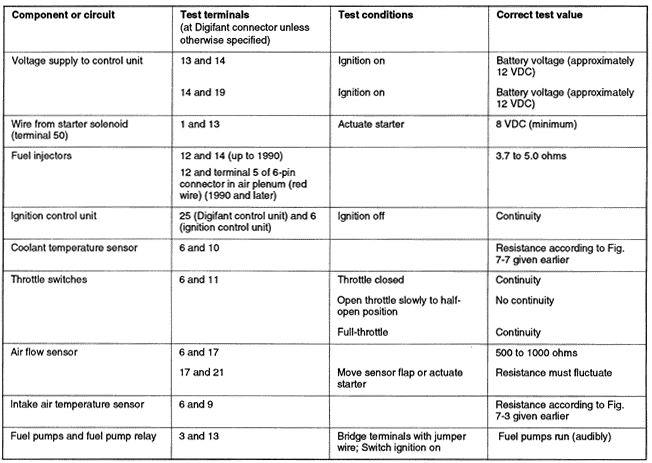
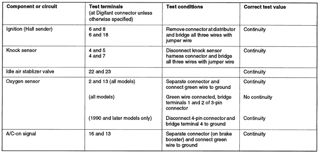
7.4 Electrical TestsThe voltage and continuity tests described under this heading can be used to help determine whether there are faults in the wiring or components which provide information to the Digifant control unit. If all control unit inputs are found to be correct and the system still does not perform as specified, the control unit itself may be faulty. As a general rule, a complete absence of the voltage or continuity specified in Table q suggests an open circuit in the wiring harness. For more specific information, see CURRENT FLOW DIAGRAMS. Test results which differ from the value specified in Table q do not necessarily mean that a component is faulty. Check for loose connections or connections which are inadequate due to contamination or corrosion.
Use care to avoid damaging the delicate connector terminals with meter probes during testing. For best and safest results, fabricate a set of test leads as shown in Fig. 7-13. Use the flat connectors (Volkswagen part no. N 17 457 2 or equivalent) to make contact with female connector terminals, then connect the meter leads to the insulated alligator clips.

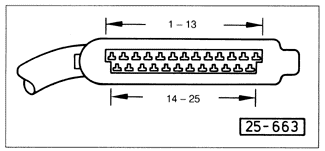
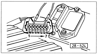
Before performing the tests indicated by Table q, disconnect the coil wire from the center of the distributor cap and connect it to ground with a jumper wire. With the ignition turned off, disconnect the 25-point connector from the Digifant control unit and the 7-point connector from the ignition control unit and test as indicated in Table q. The Digifant control unit and the smaller ignition control unit are mounted together in the upper left side of the engine compartment, beneath the drip tray. Carefully remove the drip tray for access to the control units. Remove the control unit from its mounting bracket to disconnect the control unit connector. The test terminals are identified in Fig. 7-14 and Fig. 7-15.


Table q. Digifant II Electrical Tests
|

