Idle Air Stabilizer Valve (engine codes HT, RD, PL and 9A)The electronic idle air stabilizer valve adjusts the amount of air bypassing the throttle valve to control engine idle speed. Whenever the throttle valve idle switch is closed, the valve receives signals from the control unit based on engine rpm and other inputs. This voltage signal cycles on and off. The ratio of on-time to off-time (duty cycle) determines the position of the valve and how far it is open. On CIS-E engines (not including Motronic) the valve's duty cycle can be measured at a test connection with a duty cycle meter or a dwell meter. When the idle air stabilizer valve is functioning correctly, it should vibrate and hum slightly whenever the engine is running at idle. If not, turn the engine off, check for a voltage signal at the valve's harness connector as shown in Fig. 6-30. On three-wire CIS-E systems, with the ignition on, there should be battery voltage (approximately 12 VDC) between the center terminal and ground, and approximately 10 VDC between the center terminal and each of the two outer terminals. Also check resistance at the terminals on the valve as shown in Fig. 6-30. There should be continuity between the center terminal and each of the outer terminals. If not, the valve is faulty and should be replaced. On two-wire CIS-E Motronic systems, with the ignition on, there should be battery voltage (approximately 12 VDC) between the terminal 2 and ground. Also check resistance at the connector terminals on the valve as shown in Fig. 6-30. There should be continuity between the two terminals. If not, the valve is faulty and should be replaced.

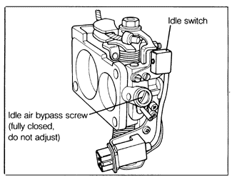
On CIS-E systems, adjustment of the idle air stabilizer system is limited to measuring the duty cycle and adjusting it to specification by adjusting the idle air bypass. See Adjusting Idle Air Stabilizer Duty Cycle below. On CIS-E Motronic systems, no adjustment is possible. Note that the idle air bypass adjusting screw on CIS-E Motronic engines should always be turned all the way in to its stop. See Fig. 6-31. A check of the idle speed stabilizer can be performed as part of an electronic diagnostic check by any authorized Volkswagen dealer. See 3.4 CIS-E Motronic Fault Diagnosis.

|