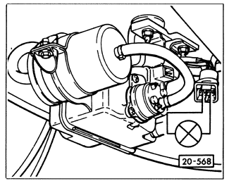
Fuel Pump Electrical TestsThe purpose of the following tests is to find out why the main fuel pump does not run. First check the fuel pump fuse. If the fuse has failed, replace it and recheck the pump. If the fuse has not failed, then the problem is most likely a faulty fuel pump relay or a fault in the wiring. The relay is actually a part of two separate circuits. One circuit is the one that powers the fuel pump-the relay acts as a switch in this circuit, switching the pump on and off. The other circuit is the one which energizes the relay with power from the ignition switch. To test the fuel pump circuit, bypass the fuel pump relay using the testing procedure described under 4.1 Fuses and Relays. If the pump runs with the relay bypassed, this indicates that power for this part of the relay is reaching the relay panel, and that the pump and the wiring to the pump are OK. The problem is in the circuit which energizes the relay. If the pump will not run with the relay bypassed, check that power for the fuel pump circuit is reaching the relay panel. There should be battery voltage (approximately 12 VDC) reaching relay terminal 30 at all times. See in ELECTRICAL SYSTEM for information on relay position and terminal identification for a particular model. If power is reaching the relay panel, check to see whether it is reaching the fuel pump. Disconnect the harness connector from the fuel pump. With the relay bypassed and the ignition on, check for voltage at the fuel pump connector as shown in Fig. 4-10. If voltage is reaching the connector, then there is a bad connection to the pump, or the fuel pump itself is faulty. If voltage is not reaching the connector, look for a fault in the wiring harness between the fuel pump relay and the fuel pump connector.

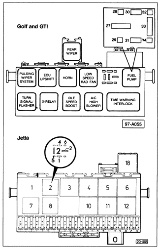
To check the circuit which energizes the relay, first check to see that power from the ignition switch is reaching the relay panel. There should be battery voltage (approximately 12 VDC) reaching the relay (terminal 15 or 86, depending on the model) whenever the ignition is switched on. See ELECTRICAL SYSTEM for information on relay position and relay panel socket identification for a particular model. If power is reaching the relay panel, check the rest of the relay energizing circuit. The test connections are different depending on the type of relay used. On cars with five-terminal relays, connect an LED test light or voltmeter to check for a voltage signal from the ignition system. On Jetta models, connect between sockets 5 and 1. On Golf and GTI models, connect between sockets 30 and 32. See Fig. 4-11. With the ignition on, there should be battery voltage (approximately 12 VDC). If not, check the wiring between the relay panel and the ignition or fuel system control unit.

On cars with four-terminal relays, connect an LED test light or voltmeter to check the relay energizing signal from the fuel system control unit. On cars with CIS-E or Digifant II (up to January 1989), connect between sockets 4 and 6. On cars with CIS-E Motronic or Digifant II or I (from January 1989), connect between sockets 2 and 3. When the ignition is turned on, there should be battery voltage for approximately 1 second. If not, check the wiring between the relay panel and the fuel system control unit. If, after the tests described above, the fuel pump will run only with the relay bypassed, as described in 4.1 Fuses and Relays, and no faults are found in the wiring to the relay, then the relay itself is faulty and should be replaced. |