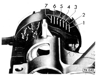
9. HornsThe components of the horn system are the dual horns, the horn relay, and the horn button on the steering wheel. On Jettas, the horns and the relay are connected to positive (+) voltage through a fuse whenever the ignition is on. Depressing the horn button activates the horn relay, which in turn completes the circuit to ground to sound the horns. On GTI and Golf models, the horn relay is also operated by the horn button, however, the horns are permanently grounded and only receive voltage through the relay when the horn button is depressed. The horn button receives voltage through terminal 71 of the turn signal switch. Two types of switches are installed on the models covered by this manual, depending on model year. Jettas up to late 1989, and 1985 through 1989 Golf and GTI models use the switch shown in Fig. 9-1. Jettas from late 1989 and 1990 Golf and GTI nodels use the switch shown earlier Fig. 8-2. Switch terminals are identified for electrical tests. On Jettas, the horn button is grounded through the same connector. On GTI and Golf models, the horn button grounds directly through its contact with the steering column. The connector is accessible by removing the steering wheel as described in SUSPENSION AND STEERING. See CURRENT FLOW DIAGRAMS for detailed information on terminal and wire identification.


|