Control Arm BushingsThe control arm and the control arm bushings are shown in Fig. 5-33. The control arm bushings are replaced by removing the control arms from the car. The rubber bushings are somewhat flexible, but they are a tight fit and a press is recommended for removal and installation. If a press is not available, arrangements should be made to have this press work done at an authorized Volkswagen dealer or other automotive machine shop. To replace the control arm bushings, raise the car and support it on jack stands. Remove the control arm mounting bolts and remove the sleeve from the rear control arm bushing. Disconnect the stabilizer bar. Remove the ball joint clamping bolt and separate the ball joint from the wheel bearing housing.
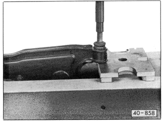
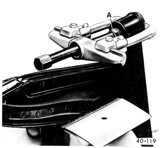
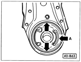
Press out the old control arm bushings, using a press as shown in Fig. 5-34. Alternately, a hand puller may be used to press out the bushings as shown in Fig. 5-35. On installation, the rear bushing must be oriented as shown in Fig. 5-36. Use soft soap to lubricate new control arm bushings for installation.


Install the control arm using a new sleeve in the rear control arm bushing. Use a new self-locking nut on the ball joint clamping bolt and torque the bolt to 50 Nm (37 ft. lb.). Connect the stabilizer bar and torque the nut to 25 Nm (18 ft. lb.). Torque the control arm mounting bolts to 130 Nm (96 ft. lb.). |