Removing and Installing Wheel Bearing Housings and Wheel Bearings
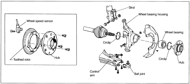
The wheel bearings are permanently sealed and maintenance-free. The bearing inner race is press-fit on the wheel hub and the outer race is press-fit into the wheel bearing housing. The bearing, therefore, is normally destroyed as it is removed. The component parts are shown in Fig. 5-24.
There are two different front wheel bearing sizes supplied on the cars covered by this manual; on 1985-1987 cars the bearing outer diameter is 66 mm (2 1/2 in.); on 1988 and later cars the bearing outer diameter is 72 mm (2 13/16 in.). The press tools shown in the illustrations are Volkswagen special tools; the tools for both bearing sizes are indicated where necessary.
Removal of the wheel bearing and installation of the new one both require a press. If a press is not available, arrangements should be made to have this press work done at an authorized Volkswagen dealer or other automotive machine shop.
Plan to use new self-locking nuts on the tie rod end and ball joint clamping bolt, as well as a new circlip to install the wheel bearing.
| Fig. 5-24. | Component parts of front wheel bearing and wheel bearing housing assembly. Bearing is press-fit in housing; hub is press-fit in bearing. Bearing is usually destroyed by removal. Inset shows hub and toothed rotor on cars equipped with anti-lock braking system (ABS). |
|
To remove wheel bearing housing:
| 1. | With the vehicle on the ground, pry off the dust cap in the center of the front wheel hub and loosen, but do not remove, the axle shaft nut. |
WARNING -
Loosen axle shaft nuts only while the car is on the ground. The leverage required to do this could topple the car off a lift or jack stand.
|
| 2. | Raise the front end of the vehicle and support it securely on jack stands. |
| 3. | Remove the two bolts holding the brake caliper to the bearing housing, and suspend it from the coil spring using a stiff wire. Remove the countersunk screw that holds the brake rotor to the wheel hub and remove the brake rotor. Also see BRAKES for more information on disassembly and assembling the brake components. |
CAUTION -
Do not allow the caliper to hang by the brake line. Doing this could damage the line and cause brake failure.
|
NOTE -
By leaving the brake line attached to the caliper, there will be no need to bleed the brake system.
|
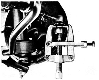
| 4. | Remove the nut holding the tie rod end to the steering arm, and use a puller to remove the tie rod end, as shown in Fig. 5-25. |
CAUTION -
The puller is used to prevent thread damage. Do not use a hammer.
|
| Fig. 5-25. | Puller being used to disconnect tie rod end (car shown is not one of those covered by this manual). |
|
| 5. | Disconnect the stabilizer bar from the control arm. |
| 6. | Remove the nut and clamping bolt holding the ball joint stud in the bottom of the wheel bearing housing, and remove the ball joint from the housing so that the control arm hangs free. |
| 7. | While supporting the bearing housing and drive axle, remove the bolts mounting the strut to the bearing housing. |
| 8. | Remove the axle shaft nut and pull the bearing housing off the stub axle. |
NOTE -
A light tap with a soft-faced mallet will help dislodge a stubborn splined stub axle.
|
Installation is the reverse of removal. The bolts and nuts that hold the strut to the wheel bearing housing are one of two sizes. Torque nuts with 19 mm hex head to 80 Nm (59 ft. lb.). Torque nuts with 18 mm hex head to 95 Nm (70 ft. lb.). Install the ball joint with a new self-locking nut and torque the clamping bolt to 50 Nm (37 ft. lb.). Torque the stabilizer bar link rod nut to 25 Nm (18 ft. lb.). Install the tie rod end in the steering arm with a new self-locking nut and torque to 35 Nm (26 ft. lb.). Remount the brake caliper to the wheel bearing housing and torque the mounting bolts to 25 Nm (18 ft. lb.). Install a new axle nut and torque it to 265 Nm (195 ft. lb.). Torque the wheel lug bolts to 110 Nm (81 ft. lb.).
WARNING -
 | Do not re-use any fasteners that are worn or deformed in normal use. Many fasteners are designed to be used only once and become unreliable and may fail when used a second time. This includes, but is not limited to, nuts, bolts, washers, self-locking nuts or bolts, circlips, cotter pins. Always follow recommendations given in this publication. For replacements always use new parts. |
 | Always loosen or tighten axle nuts while the car is on the ground. The leverage required to do this could topple the car from a lift or jack stand. |
|
To remove and install front wheel bearings:
| 1. | Remove the wheel bearing housing from the car as described above, then remove the brake disc splash shield. |
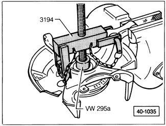
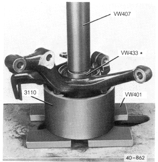
| 2. | From behind, press the hub out of the wheel bearing housing. For all models except those with the anti-lock braking system (ABS), see Fig. 5-26; for ABS-equipped models, see Fig. 5-27. |
| Fig. 5-26. | Hub being pressed out of wheel bearing housing (all models without ABS). |

|
| Fig. 5-27. | Hub being pressed out of wheel bearing housing (ABS-equipped models only). |
|
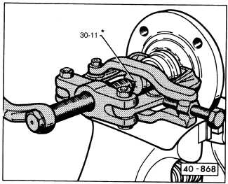
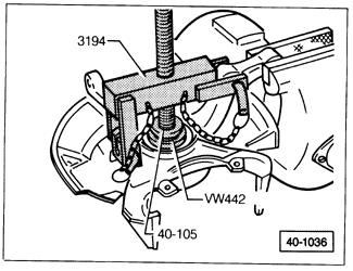
| 3. | Remove the inner bearing race from the hub using a bearing puller as shown in Fig. 5-28. |
| Fig. 5-28. | Wheel bearing inner race being removed from hub. Clamping-type puller, as shown, is highly recommended. *Use Volkswagen tool no. 40-105 for 1988 and later models. |
|
| 4. | Remove the circlips from the bearing housing on either side of the bearing outer race, and then press out the rest of the bearing. For all models except those with ABS, see Fig. 5-29; for ABS-equipped models, see Fig. 5-30. |
| Fig. 5-29. | Wheel bearing outer race being pressed out of bearing housing after circlips are removed (all models without ABS). *Use Volkswagen special tool no. VW511 on 1988 and later models. |
|
| Fig. 5-30. | Wheel bearing outer race being pressed out of bearing housing after circlips are removed (ABS-equipped models only). |
|
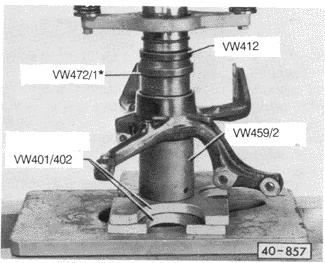
| 5. | Install a new circlip into the innermost groove in the wheel bearing housing. Lubricate the bearing seat with the molybdenum disulfide grease that is supplied with the new bearing, and press in the new bearing, as shown in Fig. 5-31, making sure to press only on the bearing outer race. Then install a new circlip in the outer groove of the housing. |
| Fig. 5-31. | New wheel bearing being pressed into wheel bearing housing. Press on outer bearing race only. *Use Volkswagen special tool no. VW511 on 1988 and later models. |
|
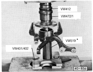
| 6. | Press the hub into the bearing as shown in Fig. 5-32. Be sure to support the bearing on the inner race only. |
| Fig. 5-32. | Wheel hub being pressed into bearing. Press tool must support bearing on inner race only. *Use Volkswagen special tool no. VW415a for 1988 and later models. |
|
| 7. | Reinstall the wheel bearing housing on the car as described above. |
|


