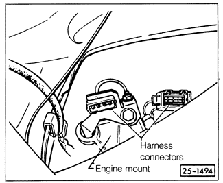
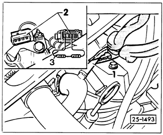
Checking Oxygen Sensor and Control Unit ResponseBecause the operation of the fuel injection system and the oxygen sensor system is integral, the basic measurement of fuel injection function-differential pressure regulator current-is also used to evaluate oxygen sensor performance. See FUEL SYSTEM-GASOLINE for information on measuring differential pressure regulator current. This is a sensitive measurement. For accuracy, the engine must be fully warmed up, the exhaust system must be free of leaks, and all electrical consumers (fan, air conditioning, lights, etc.) must be off. Oxygen sensor performance is affected by the operation of the heating element in the sensor. The heater ensures that the sensor is hot enough to generate voltage over a wide range of conditions. An oxygen sensor with a faulty heater may work fine during normal driving, when hot exhaust gases flow rapidly past it. The same sensor may not operate at idle, when it can cool. Before testing the response of the control unit, check the oxygen sensor heating function. Disconnect the oxygen sensor wiring connector, shown in Fig. 5-9. Using the appropriate wiring diagram in CURRENT FLOW DIAGRAMS to identify terminals, check for power at the connector and check the resistance of the oxygen sensor heater.

With the ignition on, there should be approximately battery voltage at the heater power terminal of the harness connector. If not, turn off the ignition and check for continuity between the harness connector and the ignition switch. Repair any wiring breaks. The resistance of the heater, checked between the correct terminal and ground, should be 3 to 15 ohms. If not, replace the oxygen sensor. To test control unit response:

|