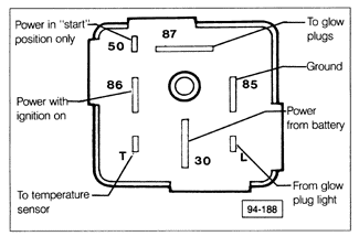
6.2 Testing and Repairing Glow Plug System CircuitsThe glow plug system circuits should be suspected if the glow plug indicator does not light, or if the glow plug bus bar does not receive voltage. A test light, or multimeter, and a jumper wire are used for testing. See the current flow diagrams in CURRENT FLOW DIAGRAMS for a complete diagram of the glow plug electrical circuits including the glow plug relay, fuses, and connector identification. The sequence of the tests which follow is important. Perform the tests in the order in which they are presented, to isolate the cause of a problem. Fig. 6-3 is a rear view of the glow plug relay used on the diesel models covered by this manual. The numbers shown appear on the back of the relay and are used to identify the terminals. In the procedures which follow, these numbers are also used in reference to the corresponding terminals on the fuse/relay panel.

|