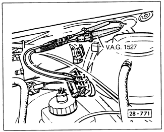
Motronic Control Unit Response to Hall Sender SignalRemove the wiring connector from the power stage and connect an LED test light between terminals 2 and 3 of the connector as shown in Fig. 3-14. With the Hall sender wiring connector connected and the coil wire still grounded, actuate the starter. The test light should flicker. If it doesn't, then either the wiring between terminal 2 of the power stage connector and terminal 11 of the control unit connector is faulty, or the Motronic control unit is faulty.

|