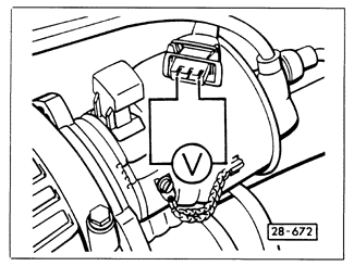
Voltage Supply and Ground to Hall SenderWith the ignition off, disconnect the Hall sender harness connector. Using a voltmeter, check for voltage between the outer terminals as shown in Fig. 3-12. When the ignition is turned on, there should be a minimum of 9 volts. Turn off the ignition. If there is no voltage, check for continuity in the wiring between terminal 3 of the Hall sender connector and terminal 30 of the Motronic control unit connector, and between terminal 1 of the Hall sender connector and ground. Repair any breaks as necessary, then reconnect the Hall sender harness connector.

|