Ignition Control Unit Response to Hall Sender SignalWith the voltmeter or multimeter connected as in the previous test, check the ignition control unit function by providing it with a simulated Hall sender signal. If the control unit does not respond as indicated, the ignition control unit is defective and should be replaced. To test the basic TCI-h system, disconnect the Hall sender connector. Turn the ignition on and, using a jumper wire, briefly connect the center terminal of the Hall sender connector to ground, as shown in Fig. 3-8. The voltage should briefly increase to at least 2 volts.

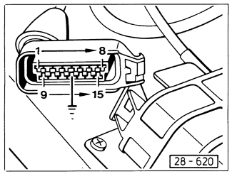
To test the TCI-h system with knock sensor, disconnect the knock sensor control unit harness connector. Turn the ignition on and, using a jumper wire, briefly connect terminal 12 of the knock sensor control unit connector to ground as shown in Fig. 3-9. The voltage should briefly increase to at least 2 volts.

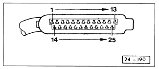
To test the Digifant II ignition system, disconnect the Digifant control unit harness connector. Turn the ignition on and, using a jumper wire, briefly connect terminal 25 of the Digifant control unit connector to ground. Terminal locations are shown in Fig. 3-10. The voltage should rise briefly to at least 2 volts.

|