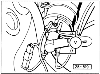
Ignition Control Unit Voltage to CoilWith the ignition off, connect the probes of a multimeter (20 DCV scale) to terminal 1 (-) and terminal 15 (+) of the ignition coil, as shown in Fig. 3-7. Do not disconnect the existing coil wiring. On models with the basic TCI-h system, disconnect the Hall sender connector at the distributor. On models with TCI-h and knock sensor, disconnect the harness connector from the knock sensor unit. On Digifant II models, disconnect the harness connector from the Digifant control unit.

When the ignition is switched on, the meter should display a reading of at least 2 volts for approximately 1 to 2 seconds, and then drop to 0 volts. If not, either the ignition coil or the ignition control unit is defective. Check the coil as described earlier in 3.2 Ignition System Visual Inspection and 3.3 Testing Coil and Spark Plug Wires. If no coil faults are discovered, the ignition control unit is faulty and should be replaced. |