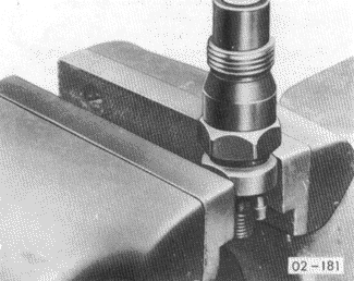
Inspecting and Repairing InjectorsMount the injector in a vise, clamping the upper body as shown in Fig. 5-27. Using a 27 mm deep-well socket, loosen-but do not remove-the lower body. Turn the injector over and clamp the lower body in the vise. The upper and lower bodies can now be separated without scattering the internal parts. Assembly is the reverse of disassembly. Torque the upper and lower bodies together at 70 Nm (51 ft. lb.)
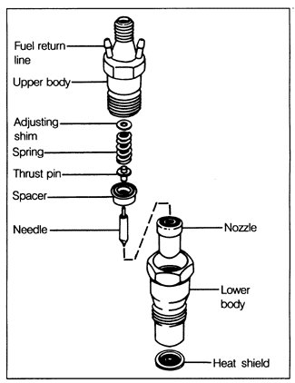
A disassembled injector is shown in Fig. 5-28. Clean the disassembled injector parts in solvent, using brass scrapers and brushes if necessary to remove hardened deposits. Take care not to scratch or damage the needle or its seat. Inspect the parts carefully-for worn or rough needle seat, worn-out nozzle bottom, cavities on the needle seat, out-of-round spray drilling, grooves and pressure marks on the needle, tempering colors on the nozzle-and replace them as required.


Test the reassembled injector's opening pressure and change adjusting shim thickness as necessary to adjust to specifications. A thicker shim increases opening pressure, and a thinner shim reduces it. An increase in shim thickness of 0.05 mm will increase pressure by approximately 5.0 bar (71 psi). Shims are available in thicknesses from 1.00 mm to 1.95 mm in 0.05 mm increments. Refer to the opening pressure specifications in Table c. Table c. Diesel Injector Opening Pressure
|
