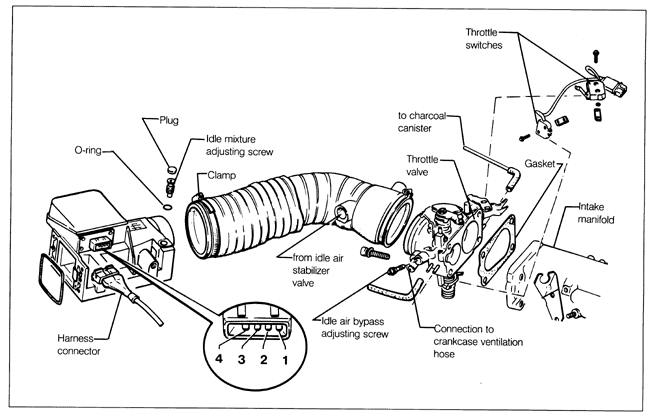
Air Flow SensorThe sensor's mechanical operation depends upon the free movement of the spring-loaded stator flap inside the main air passage. To check the flap movement, loosen the clamps, remove the rubber intake air duct, and move the stator flap through its range of travel. If the flap binds at any point, remove the intake air flow sensor, as described later under this heading, and check for any foreign material that may be interfering with the flap's movement. If the flap cannot be made to move freely, the air flow sensor is faulty and should be replaced. Check the air flow sensor potentiometer by measuring resistance across its electrical terminals. Disconnect the harness connector from the sensor and connect an ohmmeter. See Fig. 7-2 for terminal identification. The resistance between terminals 3 and 4 should be 500 to 1000 ohms. The resistance between terminals 2 and 3 should vary as the stator flap is moved by hand.

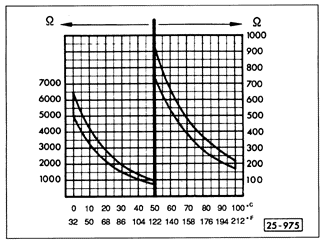
Check the intake air temperature sensor by measuring resistance between terminals 1 and 4. The proper resistance value depends on the air temperature. See the graph in Fig. 7-3. If the resistance values are not as specified for any of the tests above, the air flow sensor is faulty and should be replaced.

To remove the air flow sensor, disconnect the electrical harness connector. Remove the large hose clamp and disconnect the intake air duct. Separate the upper air filter housing from the lower air filter housing. Working from inside the upper air filter housing, remove the air flow sensor mounting bolts and remove the sensor and its gasket. Installation is the reverse of removal. Replace a gasket that is deformed or otherwise damaged. Use care not to overtighten the mounting bolts. The correct torque is only 5 Nm (44 in. lb.). |