|
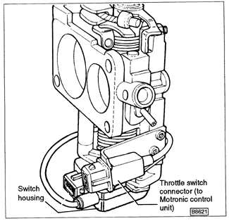
CIS-E (engine codes HT, RD, and PL only) engines are equipped with throttle position switches mounted on the throttle valve housing. These switches signal the control unit when the throttle is closed (idle) or fully open (full-throttle). The idle signal to the control unit is used for idle speed control and deceleration fuel shut-off. The full-throttle signal to the control unit is for full-throttle enrichment. CIS-E Motronic (engine code 9A) engines have idle and full-throttle switches mounted either separately on the throttle valve housing, or in one housing under at the bottom of the housing. See Fig. 6-3. Some early CIS-E Motronic engines have only a single idle switch.

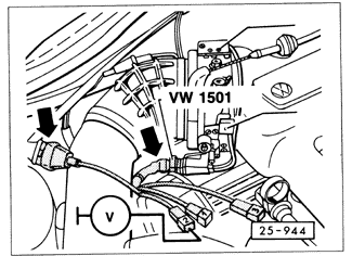
Each switch opens or closes the circuit depending on throttle position. The switch functions are checked by making continuity checks with an ohmmeter at the switch connector. Fig. 6-4 shows Volkswagen special tool no. VW 1501 (order no. TV1 501 000 24 ZEL) attached to the throttle switch connector in place of the normal wiring harness connector on a CIS-E engine. The test harness provides convenient test points, but the switches can be tested without it.

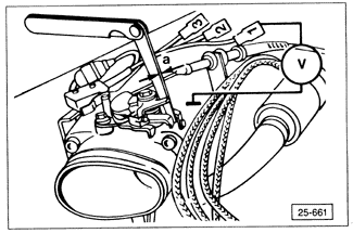
Check the idle switch by checking for continuity at connector terminals 1 and 2. The circuit should be closed when the throttle is at rest, switching open as the throttle is opened slightly. To precisely check or adjust the idle switch, open the throttle valve about half-way and slowly let it close. The idle switch should close, completing the circuit, when the gap between the throttle valve lever and its stop is 0.15 to 0.4 mm (.006 to .016 in.). Check the gap with a feeler gauge as shown in Fig. 6-5.

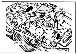
On CIS-E engines (engine codes HT, RD and PL only), check the full-throttle switch by checking for continuity between connector terminals 2 and 3. The circuit should normally be open; switching closed to complete the circuit approaching full-throttle. The full-throttle switch should close, completing the circuit, when the throttle is 10° ± 2° from full open. Check the angle using a protractor as shown in Fig. 6-6.

If necessary, the throttle switches can be adjusted by loosening their mounting screws slightly and repositioning the switch housing.
|