5. Continuous Injection System (CIS)

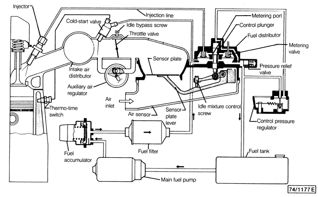
Fig. 5-1 is a schematic view of CIS fuel injection. The system is almost entirely mechanical, utilizing the influence and control of fuel pressure to accurately meter fuel. Other than the main fuel pump, electrically operated components are only used in an auxiliary role, to help adapt the fuel mixture to such extreme conditions as cold weather starting and warm-up. The continuous injection system (CIS) is so-called because, unlike many other fuel injection systems, the injectors do not open and close-they deliver fuel continuously. The main function of the fuel injectors is to atomize the continuous flow of fuel being supplied under pressure from the fuel distributor. The heart of CIS is the mixture control unit, consisting of the air flow sensor and the fuel distributor. Air entering the engine raises the air flow sensor plate. A lever connected to the sensor plate raises the control plunger in the fuel distributor, increasing the quantity of fuel flowing to the injectors in proportion to the air flow. Fuel pressure working against the control plunger, called control pressure, helps regulate the plunger's movement and pushes it back down for less fuel flow when there is less air flow. The cold start valve, the auxiliary air regulator, and the control pressure regulator are used to adapt the system to different operating conditions. The cold-start valve is like a fifth injector, and performs a choke-like function. It injects additional fuel into the intake manifold during starting to provide a richer fuel mixture when the engine is cold. The cold-start valve is operated electrically. The auxiliary air regulator opens when the engine is cold to allow a small amount of additional air to bypass the throttle plate and boost the idle speed. The control pressure regulator improves driveability when the engine is cold by reducing control pressure. This not only creates a greater pressure differential across the metering valves, causing more fuel flow for a given air flow (a richer mixture), but also improves throttle response by allowing the control plunger in the fuel distributor to rise more easily. CIS is designed so that all the auxiliary electrical components can be tested using only a test light and an ohmmeter, but the basic fuel metering system is highly dependent on fuel pressure. Evaluation of the system's basic function requires the use of a fuel pressure gauge. See 5.5 Fuel Pressure Tests and Specifications for more information. |