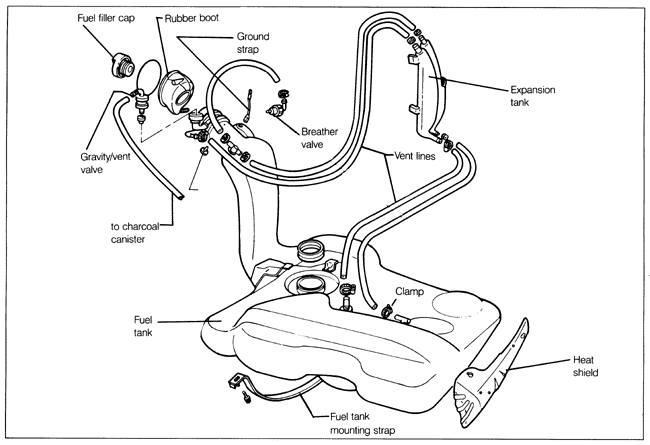
4.5 Evaporative Emission ControlsFig. 4-20 is an exploded view of the fuel tank and its evaporative emission control components. The evaporative emission system is a closed system that provides venting for the fuel tank while trapping the fuel vapors that would otherwise be vented into the atmosphere. The system collects fuel vapors from the fuel tank in a charcoal canister. Then, under certain conditions, these collected fuel vapors are vented to the engine air intake. The main components of the collection system are the gravity valve and breather valve (both located in the top of the fuel tank filler neck), and the charcoal canister (located in the engine compartment under the air flow sensor and air filter housing).

On CIS, CIS-E, and Digifant systems, venting of vapors from the charcoal canister to the intake manifold is controlled by the bypass valve (near the charcoal canister), which in turn is controlled by intake manifold vacuum. On CIS-E Motronic systems, venting of vapors from the charcoal canister to the intake manifold is controlled by a pair of electrically-operated solenoid valves operated by the Motronic control unit. The charcoal canister collects fuel vapors from the tank when the engine is idling or stopped. During normal driving, the fuel vapors which have been collected in the charcoal canister are drawn into the engine. The gravity/vent valve is connected to the charcoal canister and is normally open. In the event the car is inverted during an accident, the valve closes to prevent fuel and fuel vapors from escaping. The breather valve vents the vapors from the filler neck area to the expansion tank. The valve is open when the fuel filler cap is installed and closed when the cap is removed. This prevents the tank from overflowing and flooding the charcoal canister if the car is parked on an incline with a full fuel tank. To inspect the breather valve, remove the vent hose from the valve and connect an auxiliary hose to the valve's port. Blow into the hose. With the fuel filler cap installed, air should pass through the valve. With the fuel filler cap removed, air should not flow through the valve. To check the system for leaks between the charcoal canister and the gravity valve at the fuel tank filler, disconnect the line from the gravity valve at the canister. See Fig. 4-21. Lightly pressurize the line with a hand pump (about 1/2 psi). If the line holds pressure, there are no leaks at the bypass valve, the gravity valve, or in the lines. If the line will not hold pressure, check for leaks in the line, and check the charcoal canister bypass valve as described below. To inspect the gravity valve, first remove the valve. Working from inside the rear cargo area, pull the valve up and out of the filler neck. With the valve in a vertical position, air should pass through the valve. With the valve tilted at a 45° angle, no air should pass through the valve. |