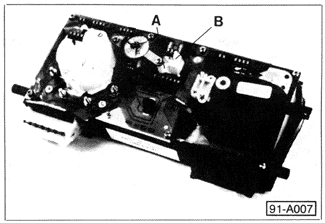
Testing Multifunction IndicatorThe multifunction indicator and its control unit are powered through the voltage stabilizer and the instrument cluster printed circuit. On some models there is an additional voltage input from the battery to the printed circuit. The control unit receives inputs for road speed, engine vacuum, oil temperature, outside air temperature, and engine rpm. It processes these inputs depending on the position of the multifunction indicator mode switch. For troubleshooting, refer to the appropriate instrument cluster wiring diagram in CURRENT FLOW DIAGRAMS. When making voltage or continuity checks of component wiring, do not forget to also test the printed circuit tracks from the wire terminal housing to the multifunction control unit. Begin diagnosing multifunction indicator problems by considering what functions are affected. For example, a complete failure of the system indicates a problem either with voltage supply or ground, or with the control unit. An inability to change modes indicates a problem either with the multifunction switch and its wiring to the control unit, or with the control unit. To test the switch, disconnect its harness connector under the steering column cover. Make continuity checks depending on switch position. Also check the wiring from the switch to the wire terminal housing connector for the instrument cluster. A problem with only the oil temperature or average speed readouts points to a problem with the sensors, the printed circuit, or the control unit. The road speed sensor is attached to the back of the speedometer housing. Similarly, a problem with the average fuel readout indicates a fault with the vacuum supply or hose from the engine, with the vacuum sensor on the back of the printed circuit, or with the control unit.

|