Replacing and Adjusting Tie Rods
Only complete tie rods are supplied as replacement parts. Tie rod ends for the adjustable right-side tie rod are not available separately. Left-side replacement tie rods may or may not be adjustable. When installing an adjustable left-side tie rod, it must first be adjusted to a standard length. Use a puller to disconnect outer tie rod ends from the steering arms, as shown in Fig. 7-5. Use a thread locking compound such as Volkswagen's D6 when installing tie rods.
| Fig. 7-5. | Outer tie rod end being disconnected from steering arm with puller to avoid thread damage (car shown is not one covered by this manual). |

|
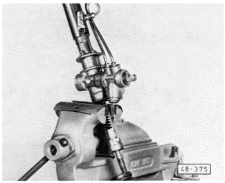
On cars with power-assisted steering, tie rod ends are torqued directly to the steering rack. Locknuts are not used. For this reason, the rack itself must be securely held when loosening or tightening the tie rod ends, to avoid damaging the steering gear. The steering gear assembly should be removed from the car and secured in a soft-jawed vise to remove and install the tie rod ends, as shown in Fig. 7-6.
| Fig. 7-6. | Steering rack for power-assisted steering mounted in soft-jawed vise for removal of tie rod. |

|
To replace and adjust (manual steering only):
| 1. | Remove the nut from the outer tie rod end in the steering arm, and press the stud out using a puller, as shown in Fig. 7-5 above. |
| 2. | Remove the clamps that hold the tie rod boots to the steering gear housing and slide the boots back over the tie rod to expose the inner tie rod end. |
| 3. | Loosen the locknut on the inner tie rod end and unscrew the tie rod from the steering rack. |
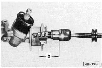
| 5. | With a new inner boot in place on the tie rod, thread the new tie rod onto the steering rack, adjusting the position of the tie rod as shown in Fig. 7-7. Tighten the lock-nut to hold this position. |
| Fig. 7-7. | Positioning new ball joint on manual steering rack. With rack centered dimension b is 70.5 mm (2.77 in.). |

|
| 6. | If installing an adjustable left-side tie rod, adjust its length by loosening the outer tie rod end locknut and threading the tie rod end in or out. Adjust the length to 379 mm (14.921 in.), as shown in Fig. 7-8. |
| Fig. 7-8. | Setting length of adjustable left-side tie rods for manual steering. Dimension c is 379 mm (14.921 in.) |

|
| 7. | On cars with manual transmission, adjust the basic right-side tie rod length to 379 mm (14.921 in.) |
| 8. | On cars with automatic transmission, adjust the basic right-side tie rod length to 381 mm (15.00 in.). |
| 9. | Reposition the inner boot on the tie rod and the steering gear housing and install the clamps. Make sure that the boot is not twisted. |
| 10. | Reconnect the tie rod end to the steering arm. Install a new self-locking nut and torque it to 35 Nm (26 ft. lb.). |
To replace and adjust (power-assisted steering only):
CAUTION-
All components of the ZF steering gear are different from those on the TRW steering gear. Do not interchange parts.
|
| 1. | Remove the nut from the outer tie rod end in the steering arm, and press the stud out using a puller, as shown in Fig. 7-5 above. |
| 3. | Remove the clamps that hold the tie rod boots to the steering gear housing and slide the boots back over the tie rod to expose the inner tie rod end. |
| 4. | Holding the steering rack securely to prevent steering gear damage, unscrew the inner tie rod end from the steering rack. |
| 5. | Clean the threads of the rack, then apply a small amount of thread locking compound (D6 or equivalent) to the internal threads of the rack. Thread the tie rod onto the rack and torque to 80 Nm (59 ft. lb.). Make sure that the boot is correctly installed and not twisted. |
CAUTION-
Avoid getting locking compound on the toothed rack.
|
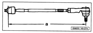
| 6. | Adjust the length of the adjustable tie rods by loosening the outer tie rod end locknut and screwing the tie rod end in or out. Adjust the length to 379.5 mm (14.938 in.), as shown in Fig. 7-9. |
| Fig. 7-9. | Setting basic length of adjustable tie rods for power-assisted steering. Dimension a is 379.5 mm (14.938 in.). |

|
| 7. | Reposition the boot on the tie rod and the steering rack housing and install the clamps. Make sure that the boot is not twisted. |
| 9. | Reconnect the tie rod end to the steering arm. Install a new self-locking nut and torque it to 35 Nm (26 ft. lb.). |
|


