Previous, Next, Contents, Home.

4.4 Valve Adjustment(1985 and early 1986 diesel and turbo diesel only)

1985 and early 1986 diesel and turbo diesel engines require periodic valve lash adjustment. A label on the cylinder head cover, as shown in Fig. 4-8, identifies the type of cam followers installed on diesel and turbo diesel engines. LUBRICATION AND MAINTENANCE gives the recommended adjustment interval. Valve clearance should also be checked 1000 mi. (1500 km) after any repairs to the cylinder head.

All other engines covered in this manual have hydraulic cam followers that do not require adjustment. To check hydraulic cam followers, see 4.6 Hydraulic Cam Followers.

Fig. 4-8. Identifying label found on cylinder head cover of diesel and turbo diesel engines requiring periodic valve adjustment.

Valve clearance is adjustable by means of a replaceable disc on the top of each cam follower. Different clearance is achieved with discs of different thicknesses. Fig. 4-9 shows the orientation of the cam lobe, the cam follower, and the disc.
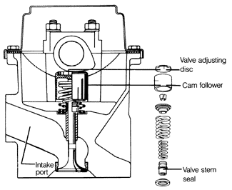
Fig. 4-9. Cross-section of cylinder head showing the cam lobe and cam follower. Adjusting disc fits in recess in follower.

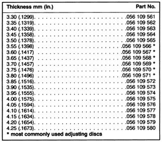
The adjusting discs are available in twenty thicknesses from 3.30 to 4.25 mm (.130 to .167 in.), in increments of .05 mm (.002 in.). Table d lists thicknesses and part numbers of the available adjusting discs. The thickness of each disc is etched on its underside. The procedure which follows requires two Volkswagen special tools. These are no. 2078, used to compress the valve spring, and no. 10-208, used to replace the adjusting disc.

Valve clearance should be measured with the engine warm. Coolant temperature should be at least 35°C (95°F) or the engine should be at least warm to the touch. The clearance changes with engine temperature, so more precise adjustment is possible when the engine is warm. Because it may be necessary to adjust the valves when the engine is cold, such as after cylinder head repairs, specifications for both hot and cold engines are given.

To adjust valve clearance:
1. Remove the cylinder head cover, as described in 4.1 Cylinder Head Cover and Gasket.
2. Using a socket wrench on the crankshaft vibration damper bolt, hand-turn the crankshaft clockwise until both the No. 1 cylinder's cam lobes are pointing approximately upward (valves fully closed).

NOTE -

No. 1 cylinder is the one closest to the camshaft drive belt.


Table d. Valve Adjusting Discs

3. Measure the valve clearances. Insert feeler gauges between the cam lobe and the adjusting disc on the top of the cam follower, as shown in Fig. 4-10. Compare the measured clearance values with the specifications given in Table e.

Fig. 4-10. Valve clearance being measured. Both valves are closed. Both cam lobes are pointing up, away from cam followers. Feeler gauge is inserted between cam lobe and adjusting disc on top of cam follower.

Table e. Valve Clearance Specifications (1985 and early 1986 diesel and turbo diesel)
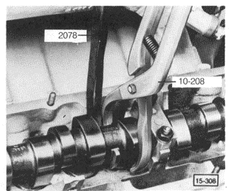
4. If valve clearance is not within the specifications, replace the adjusting disc. Depress the cam follower and lift out the disc as shown in Fig. 4-11.

Fig. 4-11. Adjusting disc being removed from cylinder head. Volkswagen tool no. 2078 is used to depress cam followers. Tool no. 10-208 is used to remove adjusting disc.

NOTE-

To calculate the correct adjusting disc thickness, first determine the thickness of the old disc. Read the thickness, in millimeters, that is etched on its underside, or measure it with a micrometer. The change in thickness required is the same as the difference between the measured clearance and the specification given in Table e. above. A thicker disc will reduce valve clearance. A thinner disc will increase valve clearance.

5. Install the correct adjusting disc. Lightly oil the contact surfaces. Depress the cam follower and install the disc the same way it was removed, as shown in Fig. 4-11, above. The etched disc thickness numbers should face down.
6. Rotate the engine by hand for two complete turns, to ensure that the adjusting disc is properly seated, and recheck the clearance.
7. Using a socket wrench, hand-turn the crankshaft clock-wise 180° (1/2 turn) and repeat the procedure on the valves for No. 3 cylinder. Turn another 180° to adjust the No. 4 cylinder, and another 180° to adjust the No. 2 cylinder.
8. Install the cylinder head cover with new gaskets, as described in 4.1 Cylinder Head Cover and Gasket.

Previous, Next, Contents, Home.