4.2 Camshaft Drive Belt (except diesel engines)
The camshaft drive belt and its related parts are shown in Fig. 4-1. Although no maintenance interval is specified, the publisher recommends periodic inspection of the belt, and replacement at 60,000 to 75,000 miles (96,000 to 120,000 km), or every 4 to 5 years. Diesel camshaft drive belt replacement can be found in FUEL SYSTEM-DIESEL.
Removal of the belt is the best way to perform a thorough inspection. Drive belt replacement does not require any special tools for most engines covered in this manual. On 16-valve engines, a special wrench is required to adjust the camshaft drive belt tensioner. On all engines, the drive belt can be replaced without removing the drive belt sprockets.
Whenever the drive belt is installed, the camshaft and intermediate shaft timing must be adjusted.
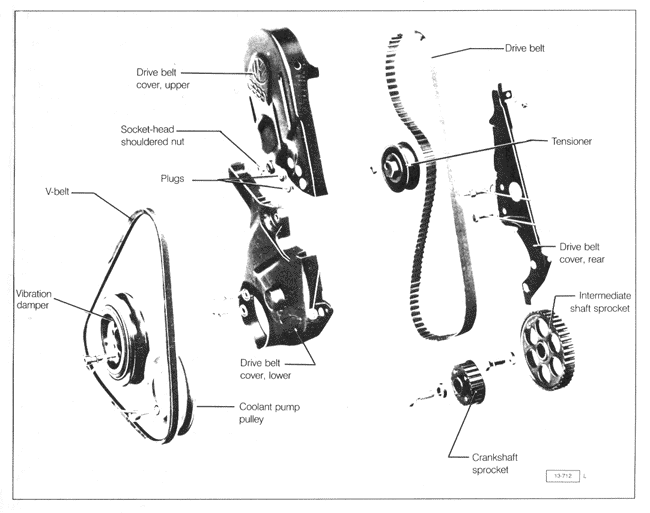
| Fig. 4-1. | Camshaft drive belt and cover. |
|
To remove and inspect camshaft drive belt (except diesel):
| 1. | Remove the socket-head shouldered nut securing the upper camshaft drive belt cover, and remove the cover. |
| 2. | Loosen the coolant pump pulley bolts, and remove the V-belts as described in LUBRICATION AND MAINTENANCE. Remove the coolant pump pulley. |
| 3. | Using a socket wrench on the crankshaft vibration damper bolt, rotate the engine by hand to set the No. 1 cylinder at Top Dead Center (TDC). Rotate the crankshaft again 1 3/4 revolutions (about 1/4 turn before No. 1 cylinder TDC). Then remove the vibration damper from the crankshaft. |
CAUTION -
Rotating the crankshaft or the camshaft with the drive belt removed may cause interference which can damage pistons and valves.
|
NOTE-
Check the position of the distributor rotor or the flywheel ignition timing marks to confirm cylinder No. 1 TDC. The vibration damper mark alone could indicate TDC for cylinder No.1 or No.4.
|
| 4. | Remove the two nuts and bolt that hold the lower camshaft drive belt cover to the coolant pump and to the front of the engine. Remove the lower cover. |
| 5. | Loosen the camshaft drive belt tensioner locknut. Turn the tensioner counterclockwise so that the tension is removed from the drive belt. Then remove the drive belt by working it off the sprockets. |
| 6. | Inspect the tensioner bearing and the belt. Spin the bearing to check that it runs smoothly. Inspect the drive belt for any visible damage such as stretch, exposed threads, missing teeth, or any other visible damage. A damaged belt or worn tensioner should be replaced. |
To install and adjust camshaft drive belt (except diesel):
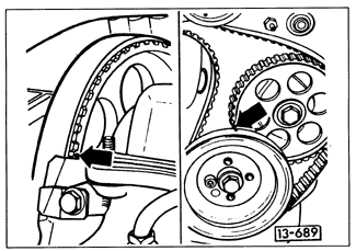
| 1. | Use a socket wrench to rotate the camshaft sprocket by hand until the timing mark is aligned. The timing marks for 16-valve engines are shown in Fig. 4-2. The timing mark for all other engines is shown in Fig. 4-3. |
| Fig. 4-2. | Camshaft timing marks on 16-valve engine. |

|
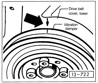
| Fig. 4-3. | Camshaft timing marks (arrows) for all except 16-valve engines. |
|
| 2. | Loosely install the camshaft drive belt over the crankshaft and intermediate shaft sprockets. Then temporarily install the crankshaft vibration damper onto the crankshaft. |
| 3. | Use a socket to rotate the crankshaft and the intermediate shaft by hand until the timing marks line up. The timing marks for the crankshaft on 16-valve engines are shown in Fig. 4-4. The timing marks for the crankshaft and the intermediate shaft on all other engines are shown in Fig. 4-3, above. |
NOTE -
It is not necessary to time the intermediate shaft on 16-valve engines.
|
| 4. | Install the camshaft drive belt. Start on the crankshaft and intermediate shaft sprockets. Install the belt so that it is as tight as possible between the crankshaft and the intermediate shaft sprockets, and between the intermediate shaft and the camshaft sprockets. |
| Fig. 4-4. | Crankshaft timing marks on vibration damper and lower drive belt cover on 16-valve engines. |
|
| 5. | Tighten the belt. Turn the tensioner clockwise and lock it in position with the locknut. Check the tension by twisting the belt, as shown in Fig. 4-5. On 16-valve engines, the belt is tightened properly when it can be twisted by hand no more than 45°. On all other engines the belt is tightened properly when it can be twisted by hand no more than 90°. |
| 6. | Torque the tensioner locknut to 45 Nm (33 ft. lb.). Turn the crankshaft two full revolutions and recheck the tension and the timing marks. |
NOTE -
Some movement of the sprockets and their marks is to be expected as belt tension is adjusted. Keep in mind that the smallest possible increment of adjustment is one whole tooth of the belt or sprocket.
|
| Fig. 4-5. | Camshaft drive belt tension being adjusted. Check tension halfway between the camshaft and the intermediate shaft sprockets. Use spanner wrench to engage holes in tensioner (inset). |

|
| 7. | The remaining installation is the reverse of removal. Remove the vibration damper to install the lower drive belt cover. On 16-valve engines, torque the upper belt cover bolt to 6 Nm (53 in. lb.). Torque all other belt cover nuts and bolts to 10 Nm (87 in. lb.). Torque the coolant pump pulley bolts and the crankshaft vibration damper bolts to 20 Nm (15 ft. lb.). Install the V-belts as described in LUBRICATION AND MAINTENANCE. |
|