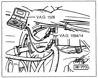
Power Stage Response to Motronic Control Unit SignalReconnect the power stage connector, then disconnect the Hall sender connector and attach a voltmeter to terminals 1 and 15 of the coil as shown in Fig. 3-15.

Turn the ignition on and, using a jumper wire, briefly connect the center terminal of the Hall sender connector to ground, as shown in Fig. 3-16. The voltage should briefly increase to at least 2 volts then drop to zero. If it doesn't, then either the power stage or the Motronic control unit is defective.

|