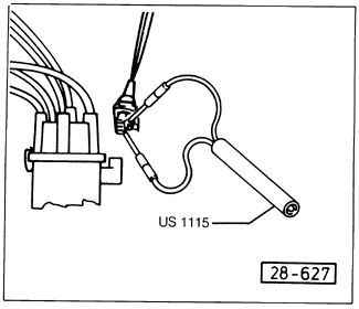
Voltage Supply and Ground to Hall SenderThe three ignition systems covered by this manual each get power to the Hall sender a different way. The basic TCI-h system powers the Hall sender through the ignition control unit. On the TCI-h system with knock sensor, the Hall sender receives power from the knock sensor control unit. On Digifant II system, the Digifant control unit powers the Hall sender. With the ignition off and the ignition control unit connected, disconnect the harness connector from the Hall sender at the distributor. Check for voltage between the outer terminals of the connector, as shown in Fig. 3-5. There should be voltage when the ignition is switched on. If there is no voltage, use the current flow diagrams in CURRENT FLOW DIAGRAMS to check the wiring between the Hall sender connector and the control unit, between the voltage source and the control unit, and between the control unit and ground. If all of these wires have continuity and there is still no voltage reaching the Hall sender, the control unit which provides power to the sender is faulty and should be replaced.

|