Control Unit InputsThe circuit information in Table u on the following page is used to make measurements at the Digifant I control unit connector, to check the components and the wiring harness which supply input signals to the control unit. As a general rule, a complete absence of the voltage or continuity specified in the table suggests an open circuit in the wiring harness. For more specific information, see CURRENT FLOW DIAGRAMS. Test results which differ from the value specified in the table, especially for values less than 10 ohms, do not necessarily indicate a faulty component. Check for loose connections or connections which are inadequate due to contamination or corrosion. Use care to avoid damaging the delicate connector terminals with meter probes during testing. For safety, fabricate a set of test leads. See Fig. 8-4. Use the flat connectors (Volkswagen part no. N 17 457 2 or equivalent) to make contact with female connector terminals, then connect the meter leads to the insulated alligator clips.

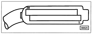
To perform these tests, turn the ignition off and disconnect the 38-pin connector from the Digifant control unit. The Digifant control unit is mounted in the upper left (driver's) side of the engine compartment, beneath the drip tray. Carefully remove the drip tray for access. Remove the control unit from its mounting bracket to disconnect the control unit connector. The connector terminals for meter connections are identified in Fig. 8-5.

When performing the tests, the following conditions apply:
|