7.6 Idle Mixture Specifications (% CO)For best results, ignition timing, idle speed, and idle fuel mixture (% CO) must be checked and adjusted together, and in that order. Final adjustment to idle mixture should be made only after idle speed is adjusted to specification. Final adjustments to idle speed should only be made after ignition timing is adjusted to specification. See IGNITION and 7.3 Idle Speed. Making these checks and adjustments together is very important to both driveability and emissions control. If the equipment necessary to accurately perform this work is not available, we suggest turning the job over to an authorized Volkswagen dealer or other qualified repair shop. In a properly equipped shop, these checks and adjustments can be made quickly, accurately, and at reasonable cost. To check idle mixture (% CO):
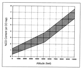
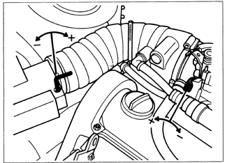
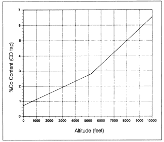
The idle mixture (% CO) is adjusted by turning the idle mixture screw, changing the amount of air allowed to bypass the air flow sensor flap. This changes the opening force acting on the flap, which changes the potentiometer signal to the control unit. Since the injector opening time (and therefore the amount of fuel delivered) is influenced by the potentiometer signal, the idle mixture is changed. The idle mixture screw can only be reached and adjusted after removing the anti-tampering plug in the top of the air flow sensor housing. This small plug is removed by drilling with a 2.5 mm (3/32 in.) drill bit and threading a screw into the plug so that it can be extracted with pliers. With the plug removed, adjust the idle mixture using a 5 mm hex wrench as shown in Fig. 7-21. Turning the screw clockwise makes the mixture richer (higher % CO). Turning it counterclockwise makes the mixture leaner (lower % CO). Adjust idle mixture to achieve the correct % CO for the average altitude above sea level according to the graph in Fig. 7-22.
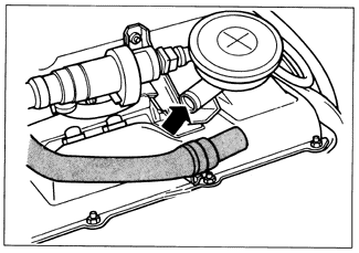
Reconnect the crankcase breather hose to the emission control valve, and replace the dipstick. Check and adjust idle speed as described in 7.3 Idle Speed.
|