|
The idle fuel mixture adjustment is only necessary if % CO is found to be outside the specified range. It must only be made by adjusting differential pressure regulator current, and only after confirming that ignition timing and idle speed are within specifications. See IGNITION and 6.3 Idle Speed. For information on measuring differential pressure regulator current see 6.1 Air Flow Measurement and Fuel Metering. CIS-E Motronic is also equipped with built-in fault diagnosis circuitry which can detect and report component faults electronically. If % CO is not within specifications, the first step should be to read the fault codes which are stored in the Motronic control unit memory. For more information, see 3.4 CIS-E Motronic Fault Diagnosis.
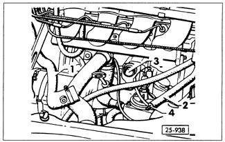
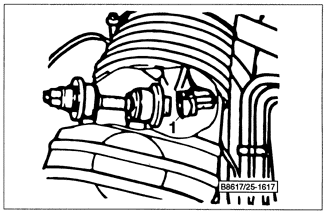
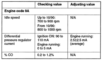
To check the idle mixture adjustment, first disconnect the crankcase breather hoses as shown in Fig. 6-55. On models built before October 1990 only, disconnect the harness connector from solenoid valve II of the evaporative emissions control system. See Fig. 6-56. Specifications are listed in Table o.


Table o. Idle Specifications (CIS-E Motronic)
|
