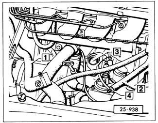
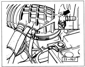
Adjusting Idle Air Stabilizer Duty Cycle (engine codes HT, RD and PL)Duty cycle describes the control unit's signal to the valve. It is the ratio of on-time to off-time of the voltage signal, and is expressed as a percentage. It is measured by connecting a duty cycle meter, such as the Siemans 451, to a test connector in the wiring harness near the ignition coil. Connect the duty cycle meter according to the instrument manufacturer's instructions. A common dwell meter can also be used to measure duty cycle. The 90° scale of a dwell meter corresponds to the 100% scale of a duty cycle meter, so multiply duty cycle specifications by 0.9 to get the corresponding value for a dwell meter. For example, a 50% duty cycle would be read as 45° on a dwell meter. The tests below express test values for both instruments. Connect a dwell meter by connecting the meter's positive (+) lead to the test connector and the negative (-) lead to ground. Fig. 6-32 and Fig. 6-33 show the temporary set-ups necessary to make accurate idle checks. Disconnect the crankcase ventilation hoses as shown. Remove the charcoal canister line "T" fitting from the air flow sensor boot and turn it to insert the side with the 1.5 mm (.059 in.) restrictor hole, as shown in Fig. 6-34. If the car is not equipped with the "T" fitting, remove the hose and fit a restrictor plug with a 1.5 mm (.059 in.) hole. Such a plug is available from Volkswagen. Ask for part no. 026 133 382D.

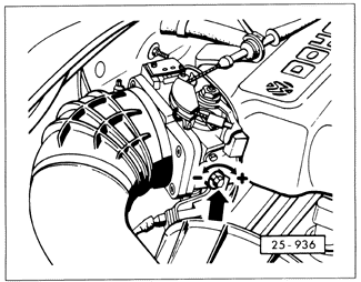
With the engine running, the duty cycle should be 26 to 30% (23° to 27° on a dwell meter) on HT and RD engines, and 23 to 27% (21° to 24°) on PL engines. If the duty cycle is incorrect, adjust it by turning the idle air bypass adjusting screw as shown in Fig. 6-35.
|