6.2 Cold Start Enrichment
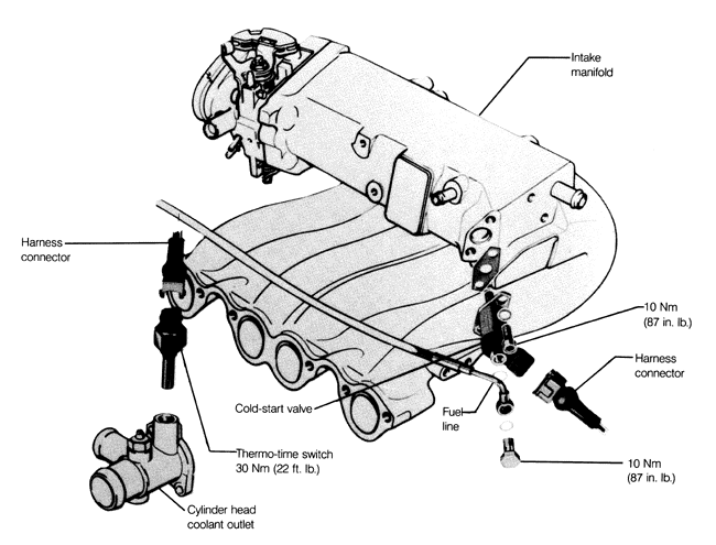
The electrically operated cold-start valve sprays extra fuel into the intake manifold for several seconds when the starter is actuated and the engine is cold.
On cars with CIS-E fuel injection, the valve is controlled by the thermo-time switch which senses engine coolant temperature. When the engine is cold the switch is closed, allowing power to reach the valve and open it. When the engine is warm, the switch is open and the valve does not operate. To limit valve operation and prevent flooding, the electric current also warms the switch and opens the circuit after a few seconds.
| Fig. 5-6. | Cold-start valve and thermo-time switch used to provide extra fuel for cold starting. |
|
On 1.8 liter 16-valve engines, the cold-start valve is located in the intake manifold and the thermo-time switch is mounted in the end of the cylinder head, as shown in Fig. 6-20. For all other engines equipped with CIS-E fuel injection, the cold-start valve and the thermo-time switch locations are the same as for CIS, shown earlier in Fig. 5-6.
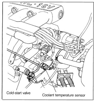
On 2.0 liter 16-valve engines with CIS-E Motronic, the cold-start valve's operation is controlled by the Motronic control unit based on input from the coolant temperature sensor. These components are shown in Fig. 6-21. The Motronic control unit controls how long the valve operates. It also controls the rate of fuel delivery, pulsing the valve to vary the amount of time the valve is open (duty cycle) by controlling the ground side of the circuit.
If the cold-start valve fails to inject fuel during cold starting, it will be difficult or impossible to start the engine. If the cold-start valve leaks, the engine may receive extra fuel at the wrong time and become flooded. This problem may especially affect hot starting.
| Fig. 6-20. | Locations of cold-start valve and thermo-time switch on 1.8 liter 16-valve engines with CIS-E fuel injection. |

|
| Fig. 6-21. | Locations of cold-start valve and coolant temperature sensor on 2.0 liter 16-valve CIS-E Motronic engines. |
|
To test cold-start valve:
| 1. | Make sure the engine is cold-engine coolant temperature below 86°F (30°C). |
| 2. | Remove the two screws holding the cold-start valve to the intake manifold. Without disconnecting the fuel line or the harness connector, remove the cold-start valve. |
| 3. | Disable the ignition system. On Motronic systems, disconnect the power output stage of the ignition coil. On all other cars, disconnect the coil wire from the center tower of the distributor cap and ground it using a jumper wire. |
NOTE-
On 1.8 liter 16-valve models, use a jumper wire to keep the metal cold-start valve housing grounded.
|
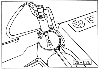
| 4. | Wipe dry the nozzle of the cold-start valve. Aim the valve into a container, and have a helper actuate the starter. See Fig. 6-22. |
| Fig. 6-22. | Cold-start valve being checked by observing fuel spray into container. |
|
WARNING-
Fuel will be expelled. Do not smoke or work near heaters or other fire hazards. Keep a fire extinguisher handy.
|
NOTE-
The valve should spray in an even, cone-shaped pattern-the length of time is determined by coolant temperature. An irregular spray pattern indicates a dirty or faulty cold-start valve.
|
Finally, wipe the nozzle dry and check the cold-start valve for leakage. The valve should not become wet or drip for at least a minute. If it does, it is faulty and should be replaced.
When replacing the cold-start valve, the sealing washers on either side of the fuel line fitting should be replaced. Torque the mounting bolts and the fuel line banjo bolt to 10 Nm (87 in. lb.).
To test thermo-time switch (CIS-E):
| 1. | Make sure the engine is cold-coolant temperature below 86°F (30°C). Preferably the engine should sit for several hours. |
| 2. | Disconnect the coil wire from the center tower of the distributor cap and ground it using a jumper wire. |
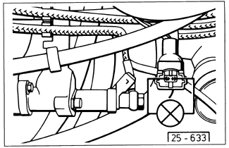
| 3. | Disconnect the cold-start valve harness connector and connect a test light across the connector terminals, as shown in Fig. 6-23. |
| Fig. 6-23. | Test light (shown schematically) connected to cold-start valve connector. |
|
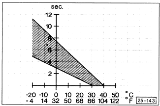
| 4. | Actuate the starter and observe the test light. It should light for several seconds, then go out. The amount of time that the light should stay on depends on coolant temperature. See the graph in Fig. 6-24. |
NOTE-
If the test light does not light, it is either because voltage is not reaching the connector due to faulty wiring, or because the path to ground (through the thermo-time switch) is interrupted by a faulty switch or wire. See CURRENT FLOW DIAGRAMS for help in identifying wires and terminals.
|
To replace the thermo-time switch, first drain the coolant from the engine as described in COOLING SYSTEM. Use a thread sealant and torque the new switch to 30 Nm (22 ft. lb.). Then, refill the cooling system with coolant.
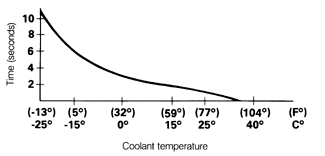
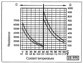
On CIS-E Motronic systems, the Motronic control unit varies the amount of time that the cold-start valve operates, according to input from the coolant temperature sensor. Fig. 6-25 is a graph of Motronic cold-start valve operating time as a function
of coolant temperature. Fig. 6-26 is a graph of resistance vs. temperature for the Motronic coolant temperature sensor.
| Fig. 6-24. | Graph of thermo-time switch response to coolant temperature. Switch completes circuit to open cold-start valve for number of seconds shown. Example: at coolant temperature of 68°F (20°C), switch is closed for 1 to 3.7 seconds. |
|
| Fig. 6-25. | Motronic cold-start valve operation (time vs. coolant temperature). |
|
| Fig. 6-26. | Motronic coolant temperature sensor specifications. |
|
| 


