Auxiliary Air Regulator
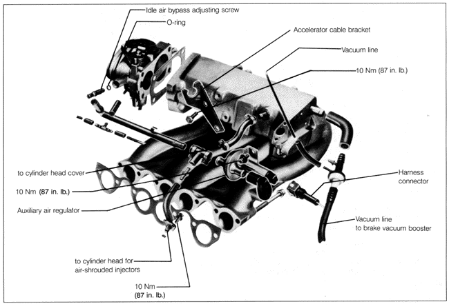
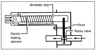
Fig. 5-16 is a schematic diagram of the auxiliary air regulator. When open, the auxiliary air regulator lets additional air bypass the throttle valve to raise idle speed. Electrical current warms the heating element and causes the bimetallic strip to deflect gradually, closing the rotary valve and cutting off the additional air. The auxiliary air regulator is mounted on the intake manifold. See Fig. 5-14 above.
Check the function of the auxiliary air regulator by checking its effect on engine idle speed under various conditions. When the engine is cold (engine coolant temperature below 30°C or 86°F), disconnect the auxiliary air regulator harness connector. Start the engine and pinch shut the hose from the auxiliary air regulator to the intake manifold as shown in Fig. 5-17. The valve should be open and the engine should lose rpm and perhaps stall. When the engine is fully warm, with the harness connector attached, pinch shut the hose as shown in Fig. 5-17. The valve should be closed and engine rpm should not change.
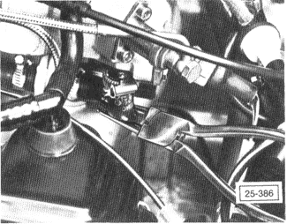
If in doubt about the results, the valve can be inspected in place using a light and a small mirror. When the valve is open (cold engine), it should be possible to see light through the valve port. When the valve is closed (engine warm), it should not be possible to see through the valve port. If the valve remains open when the engine warms, check to see that the auxiliary air regulator is receiving voltage at the harness connector. There should be battery voltage (approximately 12VDC) at the connector any time the ignition is on. To remove the auxiliary air regulator, disconnect the harness connector. Loosen the hose clamps and remove the hoses, then remove the socket-head mounting bolts. Installation is reverse of removal. Torque the bolts to 10 Nm (87 in. lb.). |