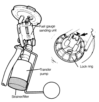
The transfer pump is mounted in the fuel tank and is an integral assembly with the fuel gauge sender. The pump is cooled and lubricated by fuel and may therefore be damaged if allowed to run dry or if the fuel pickup strainer becomes blocked. Access to the transfer pump is from the top of the fuel tank, reached from inside the rear luggage compartment.
WARNING-
When removing the transfer pump and fuel gauge sending unit, the fuel level must be below 3/4 full. If higher, fuel will be spilled when the transfer pump is removed.
NOTE-
Some 1986 Golfs and 1985-1987 Jettas have been recalled for transfer pump replacement. On affected cars, the transfer pump may seize in hot weather, causing the engine to stall. To prevent this, a modified fuel pump and filter are installed. If in doubt about whether a particular car is affected or has been repaired, check with an authorized Volkswagen dealer.
To test transfer pump:
1.
Remove the floor covering from the bottom of the luggage compartment. Remove the transfer pump and fuel sender gauge access cover by removing the three mounting screws.
2.
With the ignition off, disconnect the coil wire from the center tower of the distributor cap and connect it to ground on the engine block using a jumper wire.
3.
With the transmission in neutral, and the parking brake set, operate the starter for 3 to 4 seconds. While the starter is running, and for a few seconds afterward, the running transfer pump should be audible.
4.
If the pump is not operating, bypass the fuel pump relay as described in 4.1 Fuses and Relays.
5.
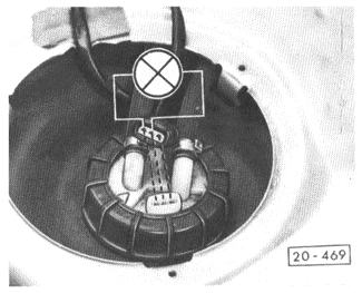
If the transfer pump still does not run, check for voltage at the transfer pump harness connector, as shown in Fig. 4-3. If voltage is reaching the connector, the transfer pump is probably faulty and should be replaced.
NOTE-
With the exception of 1985 Golf and GTI models, the transfer pump and fuel gauge sender share a common harness connector. It may have three or four terminals, depending on the model. See the CURRENT FLOW DIAGRAMS to identify the correct terminals and wires for a particular model.
Fig. 4-3.
Voltage supply to transfer pump being checked at harness connector using test light (shown schematically).
6.
If the transfer pump runs, check its fuel delivery rate. Remove the fuel filler cap. Remove and plug the black transfer pump output hose.
7.
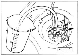
Temporarily connect a hose leading to a measuring container, as shown in Fig. 4-4.
Fig. 4-4.
Transfer pump fuel delivery rate being measured. Disconnect and plug output hose (arrow) and temporarily connect test hose.
8.
With the fuse/relay panel jumper described in 4.1 Fuses and Relays, run the pump for exactly 10 seconds. Models with CIS and CIS-E should deliver at least 400 cc (13 1/2 oz.) of fuel. Models with Digifant or CIS-E Motronic should deliver at least 300 cc (10 oz.) of fuel.
9.
If too little fuel is delivered in the preceding step, remove the transfer pump as described below and inspect the pickup strainer/filter for blockage. If the clean pickup strainer/filter is clean and the fuel delivery is still too low, the transfer pump is faulty and should be replaced.
To remove and install transfer pump:
1.
Disconnect the negative (-) battery cable.
2.
In the luggage compartment, remove the access cover and the harness connector as described above.
3.
Remove the fuel hoses and discard the hose clamps. Label the hoses so they can be reconnected correctly.
WARNING-
Fuel will be expelled. Do not smoke or work near heaters or other fire hazards. Keep a fire extinguisher handy.
4.
Loosen and remove the large lock ring on the transfer pump and fuel gauge sending unit assembly by turning it counterclockwise. See Fig. 4-5. Remove the assembly from the fuel tank.
Fig. 4-5.
Transfer pump and fuel gauge sending unit assembly shown removed from fuel tank. Inset shows how matching marks (arrow) should be aligned during installation.
5.
If the unit is to be reinstalled, inspect and clean the pickup strainer/filter. Inspect the sealing gasket on the top of the fuel tank and replace it if damaged.
6.
Installation is the reverse of removal. Place the transfer pump assembly with gasket in position on the tank with the matching marks aligned as shown in Fig. 4-5 above.
7.
Install the lock ring and tighten clockwise until snug. Using new hose clamps, reconnect the fuel hoses. Reconnect the harness connector. Reinstall the access cover, then reconnect the negative (-) battery cable.