Replacing and Adjusting Heater Control CablesThe three cables that control the heating and ventilation system are identified by their color and length. The long black cable controls the door for the instrument panel vents, the short black cable controls the heater/defroster door, and the blue cable controls the temperature blend door. If a cable or the control head is replaced, the cables should be adjusted.

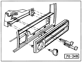
Replace control cables by first removing the center console and the lower instrument panel trays as described in 4.1 Instrument Cluster and Instrument Panel. Next, remove the control head from the instrument panel as shown in Fig. 4-5 above. Release the cable housing retaining clips on the heater box and control head, and then pull the cable off of the door control lever. Connect the new cable to the door lever, but do not install the cable housing retaining clip on the heater box. Connect the other end of the new cable to the control head as shown in Fig. 4-18, install the cable housing retaining clip, reinstall the control head in the instrument panel, and adjust the cable as described below. The remainder of installation is the reverse of removal.

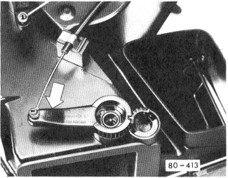
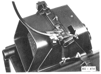
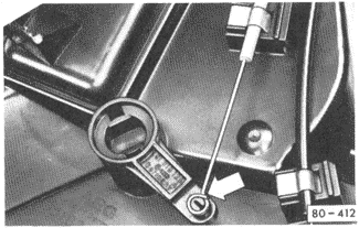
To adjust control cables, remove all of the cable housing retaining clips on the heater box. Push the levers in the control head all the way to the left. Push the heater box door levers in turn in the directions indicated in Fig. 4-19, Fig. 4-20, and Fig. 4-21, hold the levers in these positions, and install the cable housing retaining clip.


|